
Image Credit: Images #1, #2, #3, and #4: Argonne National Laboratory
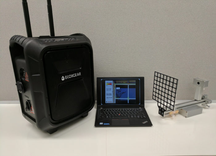
Image Credit: Images #1, #2, #3, and #4: Argonne National Laboratory Pictured here are the three components of the SonicLQ system. On the left is the commercially available high-quality speaker, which generates the test sound; on the right is the microphone array that receives the sound waves; in the middle is tablet or laptop with a screen depicting the acoustic data overlaid on a digital image of (in this case) a window in the exterior enclosure. At each intersection of the black grid is a “mems” microphone. The geometric arrangement of the microphones allows the data they transmit to be processed into an acoustic “picture” of the air leakage. The key to the ABIMS system is the two-step qualification of air leakage with far-field and near-field measurement. The SonicLQ microphone array is lightweight and rugged enough to be deployed on the exterior of large buildings attached to a drone, such as the one shown here.
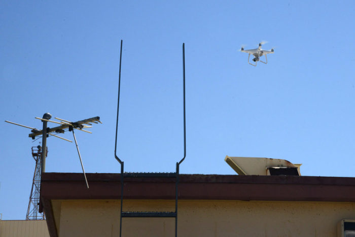
Image Credit: Image #5: U.S. Air Force photo by Christopher Ball
More Building Science


Back in the early days of airport noise mitigation programs, there was a pretty strong link between air leakage and sound. A document titled “Tips for Insulating Your Home Against Aircraft Noise” noted, “Sound travels from the exterior to the interior of the home in two ways: through solid structural elements and through the air…. Wherever air can infiltrate a home, sound can as well.”
In fact, in around 1986 — when the price of oil dropped from $32 to $11 a barrel and President Reagan slashed funding for a slew of energy-efficiency program started by President Carter — it was airport noise and the passage of the Airport Noise and Capacity Act of 1990 that served as a bit of a bridge for programs such as the pioneering Minnesota Energy Office program.
There’s an ASTM standard for that
Using sound to track air leakage is not a new idea. An ASTM standard, ASTM E1186 – “Standard Practices for Air Leakage Site Detection in Building Envelopes and Air Barrier Systems,” has longed contained an option (“Generated Sound in Conjunction with Sound Detection”) that uses acoustic information to characterize air leakage.
But note that ASTM E1186 is all about qualifying air leakage in buildings, not quantifying it: ASTM E1186 techniques are only about site detection.
The new connection: SonicLQ
Building innovatively on the sound detection option within ASTM E1186, researchers at the Argonne National Laboratory have developed SonicLQ, a system that uses sound to locate and size air leaks in building exterior enclosures (the LQ stands for Leak Quantifier).
The system can be used to test any building, during construction or after the building is completed or occupied, and during any season of the year. (You don’t need the temperature difference that infrared imaging requires). Acoustic data are presented to the user in a visual format that identifies where air leaks are located on the building façade — as well as the size of specific leaks — so that informed decisions can be made to seal the largest leaks and realize the greatest energy savings while minimizing assessment and diagnostic costs.
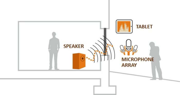
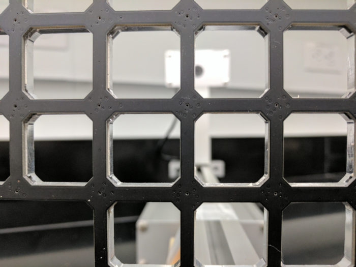
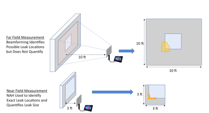
Image #1 (above) is a schematic of how the Acoustic Building Infiltration Measurement System (ABIMS) (the approach used by the SonicLQ equipment) works. Image #2 (below) shows the components. Image #3 is a close-up of the microphone array. Image #4 shows how the ABIMS is actually a two-step process.
Essentially, low-frequency sound (about 60 decibels or so, roughly the same as conversation in a restaurant or background music) is generated from the speaker and picked up by the microphone array. The sound data are wirelessly sent to a laptop computer, which translates the data into a “sound” picture, which can be overlaid with a digital one. Testing an office — one measuring about 12 feet by 12 feet — would take 2 to 4 minutes.
“Distant” acoustic measurement identifies target areas of air leakage; these measurements currently cover about 100 square feet of exterior enclosure, but the goal is to increase this significantly. The near-field acoustic measurements assess 3 feet by 3 feet areas of leakage. Summing up the identified and quantified targeted areas of leakage involves simple proportional surface geometry.
Inventor Ralph Muehleisen, principal building scientist at Argonne National Laboratory, adds, “The keys to this technology moving from a lab concept to real-world measurement are the recent advances in near-field acoustic holography (NAH) and the digital micro electrical-mechanical system (MEMS) microphones. The NAH advances have dramatically improved our acoustic capabilities while the MEMS advances have decreased their cost by a factor of ten while making the microphone arrays much lighter weight and more rugged.”
Researchers have applied for a patent
So how would this work on a two- or three-story home or a multifamily building?
The microphone array is lightweight enough that a drone can be used to track with the internal speaker location (see Image #5, below.)
Will the equipment work? Muehleisen continues, “We have published our patent application, started testing our field prototype, and have funding from the Department of Defense to do comparative field testing of conventional blower door and our ABIMS. We will be ready for pilot projects within the next 9 months.”
The new approach has promise
I decided to check in with Terry Brennan of Camroden Associates on this new technology for air leakage testing.
“This is definitely real,” said Terry. “The math holds up. I am not sure that this approach will be a real advantage over existing approaches for new, tight, buildings, but this has real promise.”
Brennan has some particular questions regarding how well SonicLQ will do with complex, circuitous air leaks — for example, air leaks through wall assemblies that include steel studs with fiberglass insulation, gypsum sheathing, and brick veneer (leaks that sometimes extend past the top of wall into a soffit or coping). He also says that the SonicLQ might do better than existing depressurization techniques for features such as trash chutes.
Brennan is also very interested in the Department of Defense comparative testing project, emphasizing how important it will be to have experienced blower door experts working with SonicLQ on the testing.
Brennan also had the following insight: “The test standard I recommend is the ABAA Standard Method for Building Enclosure Airtightness Compliance Testing. I recommend it for the following reasons:
- It was developed to be used to determine whether or not a building meets an airtightness target, including methods for determining how to interpret the results and calculated uncertainty.
- It contains requirements for building setup that includes handling things found in large buildings (e.g. elevator shafts, linen and rubbish chutes, laundries, fire egress stairwells, isolated boiler rooms with makeup air, mechanical rooms with entrances to outside and inside.
- It allows the use of E779 (multipoint shell pressure regression analysis) and E1827 (single and two point repeated reference pressure tests)
- It was developed by an ABAA committee that included testing agencies, envelope consultants, air barrier systems manufacturers, architects, engineers, test and balance contractors, and the manufacturers of blower door testing equipment over the course of three years, including two rounds of voting and two rounds of external review.
- The ABAA board of directors voted to accept and publish the standard.
I’d like to get word out about this standard, as I believe it is the best one to reference for conducting large building tests.”
NOTE from Brennan: “The only caveat regarding this ABAA standard is it’s hard to find the right place to click on the ABAA whole building test page. While you might think it should be in the list of standards in the list at the top of the page, it’s not. It’s at the end of the paragraph below that is headed ‘ABAA – Standard Method,’ where it says, ‘For a copy of this standard, click here.’”
What about long tortuous leak paths?
Gary Nelson is president and founder of The Energy Conservatory, one of the oldest companies building blower door systems. Nelson is not so sure about SonicLQ.
Nelson said, “Sonic leak detection has been around for a long time and sometimes is very useful. But [it does not] work for all types of leaks, especially long tortuous paths, sometimes going through or around sound absorbing insulation. I’m very skeptical that it will ever be able to measure the same leakage that a blower door does on a whole building. Blower door testing big tight buildings can be pretty easy.”
I will keep you posted as SonicLQ is put through its paces in the field in the upcoming year.
In addition to acting as GBA’s technical director, Peter Yost is the Vice President for Technical Services at BuildingGreen in Brattleboro, Vermont. He has been building, researching, teaching, writing, and consulting on high-performance homes for more than twenty years. An experienced trainer and consultant, he’s been recognized as NAHB Educator of the Year. Do you have a building science puzzle? Contact Pete here. You can also sign up for BuildingGreen’s email newsletter to get a free report on avoiding toxic insulation, as well as regular posts from Peter.
Weekly Newsletter
Get building science and energy efficiency advice, plus special offers, in your inbox.


11 Comments
Progress testing
I could see this technology being very helpful on large commercial projects. Typically we have a hard time doing blower door testing during construction because of trade sequencing. The first floor of a building might be fully clad while exterior foam is still being installed on an upper floor. By the time the building is fully air sealed, much of the air barrier is concealed. We do our best to test components and pieces of the assembly, but the acoustic approach could be a good supplemental approach.
Interesting. I wonder how it
Interesting. I wonder how it compares to some high flow source of fog directed against partitions (think smoking leaf blower).
Image 2 mix-up
Should the caption not indicate speaker on the left and microphone array on the right?
Response to Antonio Oliver
Antonio,
Thanks for catching the error. I have made the necessary correction.
Units problem
"Essentially, low-frequency sound (about 60 decibels or so, roughly the same as conversation in a restaurant or background music) is generated from the speaker and picked up by the microphone array."
Frequency is measured in hertz, intensity is measured in decibels. It's possible to have very high or very low frequency at very high or very low intensity. So what is that statement supposed to mean?
Since the units used were decibels I'll assume intensity, but I'm also curious about the frequency used, since the degree of acoustic attenuation of building materials varies with frequency, and a room's dimensions also have characteristic resonance frequencies that can affect the measurement.
Units Problem
Good catch Dana.
Here is SonicLQ inventor Ralph M's response:
"The statement I gave is indeed confusing. The 60 dB is, as you surmised, the sound pressure level (i.e. related to intensity or volume) but the sound is also a low frequency tone in the 50 to 200 Hz range. The frequency chosen will depend upon the background noise (we try to choose one without interference) and one that isn’t at a room resonance frequency (of which there are many in the 50 to 200 Hz range for most rooms)."
Makes sense. @ Peter Yost
Thanks for satisfying my curiosity!
It makes sense that they would need to vary the frequency to be able to tune out resonance & interference issues. A quarter wave of 100 Hz is about a yard and any unit-multiple of a quarter wave can "ring" creating a higher intensity and possible mis-calibration of the hole size, etc. In a given room there are many frequencies between 50-200 Hz that will have the issue, but in most rooms you'd also be able to find many frequencies that don't (much).
Even better is a standalone
Even better is a standalone square wave or filtered square wave pulse pulse - no resonance. Repeated to improve signal to noise.
Square waves are a combination of the odd harmonics
It'll definitely resonate!
The fidelity of the squareness of the wave that gets out will also be distorted by the path's length and shape.
Reflected sound is ignored in
Reflected sound is ignored with a time window - so no room resonance effect in the result. The single "impulse" pulses are far enough apart that they don't interfere with each other.
With cheap FFT, a continuous sine wave (which may or not be the case here) is one of the worst ways to measure sound attenuation along a path.
MLS stimulus may be better than impulse, but I haven't used it.
Room Resonances and Use of Non Pure Tones
Room resonances are only a problem if the interior microphone is at a room node. The person working inside could sense that and move the microphone. The ideas to use non-pure-tones (various types of pulses or MLS) iare good ones and the research team is working on that right now.
But, the field demos will concentrate on using tones because it's much easier to do the nearfield holography processing and the conversion of acoustic to infiltration data on pure tones. The method is not just trying to find the sound transmission loss across the enclosure so the team would need to make some serious changes to the NAH and other algorithms.
(Note: I am one of the technology inventors)
Log in or create an account to post a comment.
Sign up Log in