
Image Credit: Alex Wilson
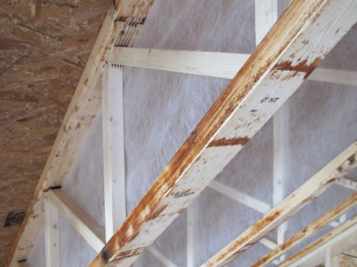
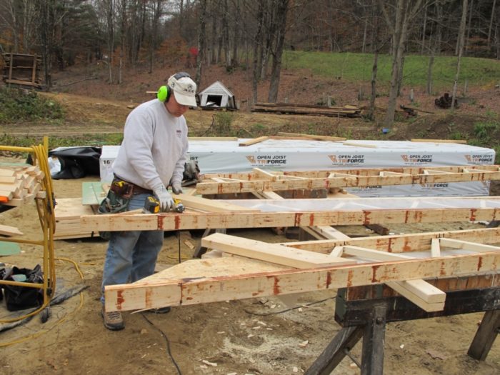
Image Credit: Alex Wilson The Triforce joists are made with solid-wood diagonal struts and glued, finger-jointed connections.
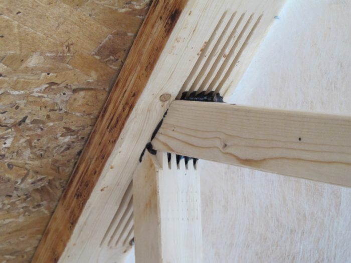
Image Credit: Alex Wilson Detail showing finger-jointed glue joint.
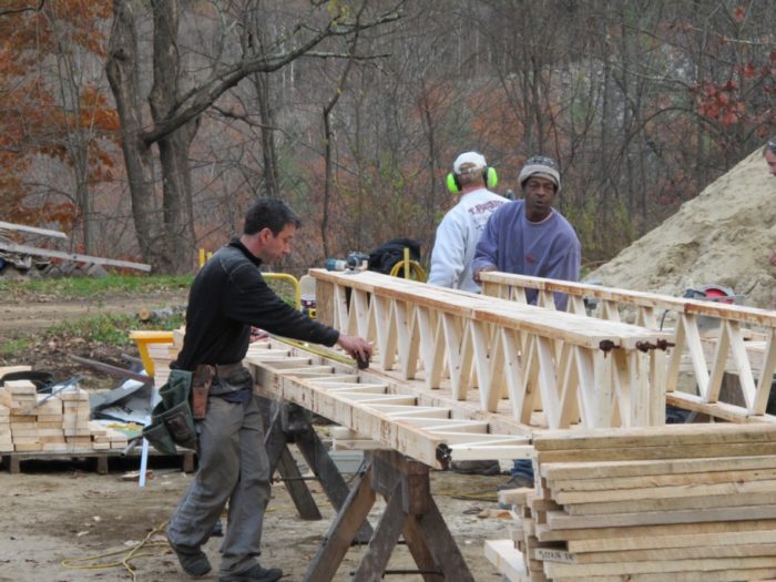
Image Credit: Alex Wilson Prepping rafters for installation. We added raised heels to gain additional space on the second floor.
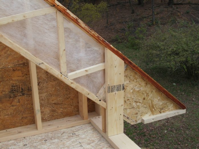
Image Credit: Alex Wilson We think the fabric will help us achieve complete filling of the rafter cavity with fiber insulation. You can see the "foot" on the rafter in this photo.
Image Credit: Alex Wilson Fabrication detail showing how loads extend down through the 2x6 "heel."
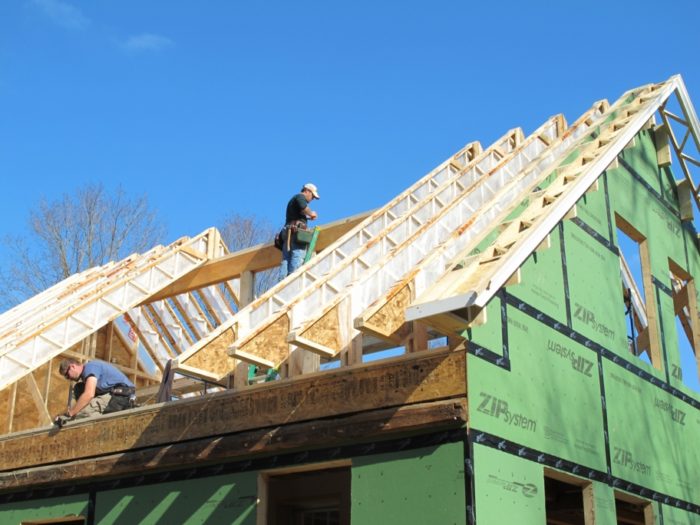
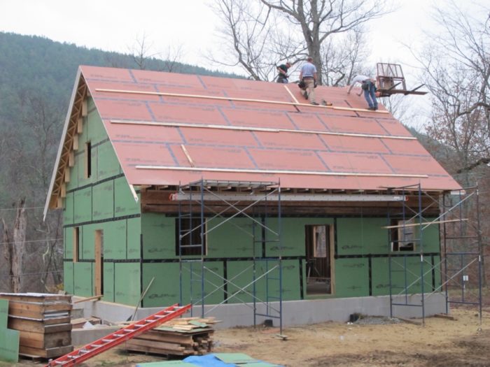
Image Credit: Alex Wilson Racing Sandy to get the last of the roof sheathing up. A dormer was later cut into the roof.
Image Credit: Alex Wilson
More Energy Solutions


Last week I wrote about an innovative foundation insulation material, Foamglas, that we used in our new house in Dummerston. This week I’ll talk about the open-web rafters we’re using to achieve a superinsulated roof.
First, a little background. There are several approaches to creating highly insulated roofs.
When the insulation is installed in the attic floor (creating an unheated attic), it’s easy to obtain very high R-values inexpensively — it’s cheap, that is, as long as you don’t count the cost of the lost living space by creating an unheated attic. Basically, you just dump in a lot of loose-fill cellulose or fiberglass on the attic floor, filling the joist cavity and more.
I’ve heard of as much as two feet of cellulose insulation being installed in this manner, achieving about R-80. To make room for a lot of insulation at the roof eaves, it’s usually necessary to install “raised-heel” trusses for the roof framing, so that the insulation thickness at the edges is not significantly compromised.
If you want to insulate the sloped roof, creating living space — as we are doing — you can either install very deep rafters (14 inches or more) that can be filled with cavity-fill insulation, or you can provide more modest roof trusses or rafters and then add a layer of rigid insulation on top of the roof sheathing. An advantage of the latter approach is that the layer of rigid insulation controls the “thermal bridging” through the rafters or top chords of the roof trusses.
To keep the insulation costs down and to minimize our use of foam-plastic insulation, we opted for the former option — putting all our insulation in the rafter cavities rather than installing a second layer of outboard insulation.
Finding deep enough rafters
To achieve the 16-inch depth we wanted for insulation and an air space under the sheathing, we used open-web, parallel-chord trusses as the rafters. These trusses, typically used as joists, have diagonal bracing or “struts” and are made in Quebec by Open Joist Triforce.
Unlike most parallel-chord trusses, Tri-Force uses solid wood, rather than OSB, and finger-jointed glue joints rather than metal truss plates for attaching chords and webs. Some experts are concerned about the long-term durability of OSB webs in more common I-joists and the metal fasteners in standard roof trusses.
The chords on Triforce joists are either 2x3s or 2x4s, and the diagonal struts are solid-wood 2x2s, allowing vent baffles to be attached to the top chord (providing a 1-1/2″ vent space). Connections between the struts and chords are achieved with precision-machined grooves and polyurethane adhesive. The wood is all northern, slow-grown spruce, rather than plantation-grown southern yellow pine or poplar.
Triforce joists include a section of OSB at the ends so that the length can be adjusted. This permits manufacturing in standard lengths and keeps the costs down.
Providing a stem wall and roof overhang
In our case, to expand the living area in the upstairs of our compact house, Eli Gould added “raised heels” to the roof trusses. The OSB tails on the Triforce rafters made this fairly straightforward, though it certainly involved some additional labor. The design at the roof eaves also provides for nearly two feet of roof overhang — a high priority in keeping moisture off the wall and away from the windows and foundation.
Despite the extra work with the raised heel and overhang, the rafters went up quickly. Eli’s crew worked all day on the Saturday before Superstorm Sandy came through to get the roof up and sheathed with Huber’s Zip sheathing (with joints taped). They were able to keep everything remarkably dry.
Insulation options
We have not made a final decision about the type of insulation we will use for the roof. We are deciding between dense-packed cellulose and acrylic-stabilized, blown-in fiberglass (probably Johns Manville Spider). With 14 inches of insulation (allowing for the vent space under the sheathing), the difference in weight between cellulose (at about three pounds per cubic foot) and Spider (1.8 pounds per cubic foot) is significant.
With either material, we believe that by stapling up mesh-fabric baffle on each rafter we will be able to fill each rafter cavity (up to the vent space) completely — including all the corners where the diagonal struts intersect the chords. The small amount of acrylic adhesive in the JM Spider product may prove to be a significant benefit to us in fully sealing the cavities — so we’re leaning in that direction.
The two materials provide similar insulation values: about R-4.1 to 4.2 per inch for the JM Spider fiberglass and about R-3.7 per inch for dense-packed cellulose. With 14 inches of insulation, that would come to about R-58 with JM Spider, vs. R-52 with dense-pack cellulose.
From an environmental standpoint, cellulose has a higher recycled content (about 80% recycled newspaper), though fiberglass insulation is now made using a significant amount of recycled glass (mostly from beverage containers). Johns Manville fiberglass is certified to have a minimum 25% recycled glass content (with 80% of that recycled content being post-consumer).
Flame retardants are not required in the fiberglass, while borate and ammonium sulfate flame retardants are used in cellulose.
Here’s the product listing in our GreenSpec database.
Alex is founder of BuildingGreen, Inc. and executive editor of Environmental Building News. He also recently created the Resilient Design Institute. To keep up with Alex’s latest articles and musings, you can sign up for his Twitter feed.
Weekly Newsletter
Get building science and energy efficiency advice, plus special offers, in your inbox.


23 Comments
Raised Heel
Minor detail. In the photo of the "raised heel," is there solid blocking directly under the web rafter or are the vertical 2" x 6"s (raised heel) notched around the bottom chord and butted up against the underside of the top chord? Otherwise it would seem the roof loads would rely solely on the shear strength of the nails/ screws. Just curious.
Structural loads at the rafter heel
Dave,
I added another photo that shows the construction of the rafters more clearly. I hope that answers your question. Timber engineer Ben Brungrabber, P.E., Ph.D., has been advising Eli on structural design issues with this new application of parallel-chord trusses.
Other Options
I use a deeper vaulted parallel chord truss 24 to 28" so I can get more insulation and clear span. They are made from 2 x 4's with gusset plates like conventional rafters.
Doug,
I'm replying to a very old post, but I'm intrigued by your alternate parallel-chord truss design using deeper 24" or 28" trusses. When you say "clear span" does that mean you're able to eliminate the need for a ridge beam like conventional rafters?
Deep roof with dimensional lumber
We came up with a simpler detail - use whatever depth dimensional lumber the load calls for (typically 2x8 or 2x10), then take some scrap plywood and make some gussets about 2-3" wide by whatever depth you want overall (we typically go with 14"). We use 2x3's for the bottom chord, usually making our own by ripping 2x6 in half, and fasten the gussets perpendicularly, one every 2-3' and alternating sides of the 2x3. Then you shove the assembly up so the gussets hit the underside of the roof sheathing and nail into the sides of the rafter.
You are left with a deep assembly with a very good thermal break in the middle (with 2x8's, you'd have 5" of solid cellulose in between rafter and bottom chord).
I wrote a piece about the house we first used this assembly on - you can see it here - http://www.kaplanthompson.com/_images/publications/09.06-jlc.pdf Which, coincidentally, also has a picture of Diane Milliken conducting a blower door test (the photo in Allison's blog this week)
Metal Truss Plate Question:
Alex,
What do you mean when you say that some experts are concerned about the long term durability of metal fasteners (truss plates) in standard roof trusses? What problem with durability do they anticipate?
Response to Ron Keagle
A picture or two is worth a thousand words.
.
What is causing that?
What is causing that?
Response to Ron Keagle
Ron,
Probably a variety of factors, ranging from twisting and stress incurred during the installation of the trusses, to manufacturing errors, to overloading, to stresses induced by seasonal variations in the moisture content and temperature of the lumber.
Wow, I have seen lots of
Wow, I have seen lots of nailed in place rafter ties coming off ( I bolt them now) but never one metal truss plate.
Alex, nice useful blog.
I am skeptical of the
I am skeptical of the suggestion that metal truss plates are not durable enough. Seasonal changes in humidity should not cause any problem with the truss plate connections. Storing trusses outside for prolonged periods may cause the plates to lift due to repeated rain wetting.
I suspect that the damage shown in the photos was caused by improper handling during installation, and the trusses were not repaired. It appears that the trusses may have been set, and then fallen over before they were temporarily braced. Falling over may have bent them sideways across the span when they laid over on their sides. That kind of bending stress could create sufficient tension to pull a plate out of the lumber on one side of the joint.
Ron
I agree. There may be valid reasons to be wary of OSB I joists but engineered metal connections on trusses have a track record going back decades. Failures in properly designed and installed trusses are unheard of.
Structural loads at the rafter heel
Alex,
The picture does clarify how the load is transferred to the plate. Just my 2 cents but I'd jam a solid block directly under the rafter and in between the two 2x6s. I've been told I have a tendency to overbuild though....
Roof Ventilation
How do you plan to do the air space for the roof ventilation? Are you planning to attach plywood to the underside of the top chords and air seal the joints?
Air sealing
James,
Yes, we plan to attach plywood (or some other material) to the underside of the top chords. I don't think we've decided on the baffle material, and I'm not sure what the air-sealing plan is. Do you think the plywood (or other material) needs to be air-sealed to the rafters?
Dave, I'll make sure that Eli sees your comment on blocking. I'm not sure exactly how that was handled.
Truss to Heel Leg Connection
I would think that raised heel would need to be engineered because it converts the vertical load to a shear load between the truss and the vertical 2 X 6 legs; due to the inclined contact between the top of the legs and the bottom of the top chords. The resulting shear load is borne by the nails, perpendicular to them. That shear load will try to tip the tops of the legs toward the ridge line.
I was once told that the engineered portion of the truss had to bear in a horizontal plane upon the tops of the studs. So, in this case, the engineered portion of the truss includes the raised heel legs.
Air sealing
Alex
I was also wondering what your air barrier plan will be. The temptation might be there to designate the Huber Zip roof sheathing as the air barrier as it is already taped and airtight. One problem there, is that the taped joints are not easily inspectable or repairable. The other big concern comes when it is time to reroof....thousand of nail holes. Airtight drywall might work for you though, especially if the drywall can go up before the interior upstairs wall partitions...
Design/builder for Alex joining forum
The comments and questions on this forum were so excellent that I told Alex yesterday I'd sign up and weigh in with a couple responses even though I won't be able to spend much time here. This structural system has been one good innovation among many on the building, but it isn't quite a "system" yet so I'm going to share/reassure some of the structural strategies we used but really only to overbuild a first prototype and spark the sort of conversations and product development which are now happening....The manufacturer is also very interested in what we are trying to do and our hope is that by leading the way here that there will soon be available a solid wood, FSC certified, northern forest produced parallel chord rafter system. ..but this is just the first step. Engineering wise, we did notch and key right into the bearing block that the manufacturer uses to transition from OSB trimmable portion into the diagonal struts. The fastening through the OSB may help with some lateral strength but isn't bearing, nor is the top chord doing so on its own. We are using the top chord space for not only overhang structure but also ventilation, and I welcome everyone's expertise on the building science of that as I've done it both ways but am deferring to various expert inputs on this project. I have to say, I've known Alex for years, as well as the engineering team and staff that has contributed to our design/build process, but I have not spent any time on this site and I am impressed and heartened by all the good comments, criticisms, and most of all the interest. Thanks, and off to work for me!
Roof Venting
We have experimented with using cellulose netting as a "stop" for blown in insulation (cellulose). We stapled the netting between the top chords of the trusses ~ 1" below the roof sheathing in each truss bay. This approach worked very well. We did not find it necessary to separate the areas between the trusses as you have done, the cellulose moved easily between the web members and the cavity was filled to a very high density (we measured ~ 6 lb / cu. ft.) The exterior side of the netting takes on a hard "slippery" property that air moves over easily, so easily that it would be a good idea to be cautious about where the air is directed to. The "netting stop" is cheaper and easier to install than plywood or preformed foam stops.
Mounting these trusses as
Mounting these trusses as rafters raises questions.
In reviewing Dave’s question in post #1, the nails would obviously be carrying the entire load in shear if the truss did not bear on top of the pair of short studs. But the one photo added to respond to his question makes it clear that the truss does bear on top of the studs.
However, the nails are still carrying a significant portion of the load in shear as a reaction load. In other words, if this were assembled, and the nails were to magically disappear, the 2 X 6 studs would move with slippage along their sloped contact with the truss.
Normally, I would expect this detail to be made by having the studs support the truss with the point of contact being in a horizontal plane. With a manufactured scissors truss, the heel of the truss is made by running the bottom chord horizontal for a short distance at the wall support point. And that horizontal portion is properly supported by a strut from the top chord. So the horizontal feature of the truss is part of the engineered truss. It seems to me that the open web trusses used in this house would require the same type of horizontal feature that would be an integral part of the engineered truss.
But without that engineered pedestal feature of the truss that would provide a horizontal load bearing surface, a builder would need to custom build it as is the case with these truss rafters supported by the 2 X 6 studs. And that custom work would need to be engineered to account for all the forces. I would think that the connection would require something like 2 x 2 cleats screwed and glued to the bottoms of the top chord in a way to prevent the 2 X 6 studs from tipping toward the ridge as a reaction to their vertical loading through the sloped contact surface. Such cleats would take all of the shear loading off of the nails.
I do not fully understand how this detail is executed at the ridge, but there, the reaction force on the studs opposes the same force from the opposite side of the ridge. So if the short 2 X 6 studs on each side of the ridge were contacting each other, they would each compensate the other’s reaction force. I cannot tell from the photos if they are contacting each other.
Airtight detailing
The real question is, how are you getting this roof airtight?
Airsealing the plywood between the trusses is way to complicated IMHO.
Wind washing of fiberglass will reduce the r-value significantly (see http://www.bbacerts.co.uk/media/111797/air_movement_report.pdf)
I have easier solutions (aka service cavity), which could also enable you to get rid of all your plastic insulation (ie foam). By venting the roof above a vapor open roof membrane (including Solitex mento
Membranes which we supply with http://www.foursevenfive.com
Truss Config, Roof Venting, & Air Tightness
Thanks very much Alex for posting on these options, innovations, and alternatives you've explored in the design and build of your home. I also appreciate your honesty about answering forthrightly - if the question asked is one you haven't encountered or solved yet. I most enjoy these blogs as information exchanges - where pieces to important puzzles can be fitted together to benefit all.
Doug, I agree with your observation about a different parallel-chord truss configuration, especially one that would negate installation of a ridge beam. Having the two framing systems available to consider (the one you and Eli are using here, Alex - as well as Doug's) are valuable.
Eli, interesting use of trusses at the rake locations. I can see the time/ labor savings in that approach.
Kim, I would favor the netting stop you suggest. Relatively easy to install, inexpensive, and performs well both in allowing ventilation air to pass under the structural roof sheathing, and in allowing moisture from below to migrate out as necessary. I've seen the foam baffles installed all the way up the underside of the sheathing, allowing for one function but blocking the other. So your solution is one I favor for deep cavity-fill sloped applications.
Alex, you make mention, and Kim mentions, density of insulation fill material. You mention you are likely to install the lighter JM Spider fiberglass fill with acrylic binder. This strikes me as a better choice than a light or medium-density cellulose fill. I would be concerned with long-term downhill settling of cellulose on the roof pitch you have, potentially creating uninsulated voids at the ridge.
The detailing of the air barrier sounds like one you are wrestling with now, Alex. We favor application of either an air barrier membrane like Solitex mentioned above, or a rigid barrier attached to the bottom of the bottom chords (a sub-ceiling, if you will, that can be taped and detailed). Of course handling penetrations at this air barrier location has to be thought through, but it is very doable with care and inexpensive materials. We have also used gypsum sheetrock as an air barrier at this ceiling location, and achieved 0.9 ACH50 results without much trouble (and had to deal with owner-selected recessed can lights, to boot). The air-tight drywall approach isn't perfection incarnate, but then what are your target air-tightness results Alex ? (expressed as either ACH50 or - in a nod to Allison, ELR)
re roof venting: I'm agonizing about roof venting on a roof on parallel chord trusses with a 3.5/12 slope which I have nearly finished installing in Quebec. My original plan was to use Tentest (asphalt impregnated fiberboard) 2 inches below and between the tops of the trusses. Unfortunately the truss manufacturer dropped the last three trusses on the the gable ends to support my 30 inch overhangs. That left 8 inch deep and six foot wide barriers to airflow every two feet. I finally decided on a two layer roof with an inch and a half gap between the tentest and the plywood decking on top. Tentest has a 17 perm rating so I think it will keep the cellulose out ot the vent space, prevent windwashing and hopefully drain any roof leaks to the outside of the building. We'll see how that goes for the installation. My wife and I are both in our seventies and not quite as nimble as we used to be. To save money on the truss bill I went with 2x10 rafters on the small roof with a 2/12 slope and an 11 foot span. This roof (not cathedral) will have two feet of space above the two feet of cellulose on the high side but not on the low side. All four walls on the house have six feet amputated from both ends and are joined with an eight and a half foot diagonal wall at 45 degrees. The 6'x6'x102 inch triangle has dead end rafters spanning vertically to horizontally which will not be vented unles I pierce holes in the rafters. (Both roofs are on a single plane.) I have already installed 5/8 T&G plywood decking on the small roof and am reluctant to remove it to vent it in the same manner as the larger roof. Is my only option another plywood roof with inch and a half spacing below? I haven't figured out how to upload drawings yet. I hope the description will suffice. Thanks. Nils
Log in or create an account to post a comment.
Sign up Log in