

Image Credit: Photos and illustrations: Michael Hindle and Carri Beer
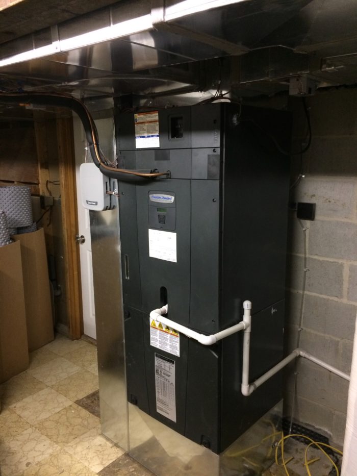
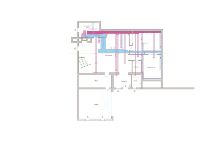
Image Credit: Photos and illustrations: Michael Hindle and Carri Beer A pair of gas-fired furnaces was replaced with an American Standard air-source heat pump and this two-zone air handler. The white pipe at the front of the unit is a condensate line for the cooling coil. Supply (red) and returns (blue) for the lower level of the house as they were when the authors bought the house. In the reconfigured HVAC system, the lower level of the house is divided into two heating and cooling zones. On the first floor, there are three heating and cooling zones. Two of them, on the east and west, are handled by a new air-source heat pump. The south zone will be served by a 1-ton, wall-mounted ductless minisplit.
More Guest Blogs


Editor’s note: Carri Beer and Michael Hindle are renovating a 1954 house in Catonsville, Maryland. Hindle is a Certified Passive House Consultant and owner of Passive to Positive. Beer is a registered architect who has been practicing sustainable architecture for 18 years. She is an associate principal with Brennan+Company Architects. This post details Michael’s redesign of the HVAC system. For a list of the couple’s posts, see the “Related Articles” sidebar below.
Perhaps this says something about the author, but the HVAC retrofit/replacement has been one of the most fun aspects of this project. When we toured the house it was apparent the heating and cooling systems were configured and sized simply to overwhelm any possible deficiency of the building. They were not only vastly oversized, but very strangely configured and in poor condition.
The inspection report said the systems were functional. This was stretching the definition of “functional,” as we soon learned, but to a naïve optimist, every challenge looked like a cool opportunity.
There were actually two systems: one for the original house and the south-side sunroom, and a second one for the large living room addition over the garage. The system serving the addition was very straightforward: just a big old gas furnace and cooling coil in an air-handling unit (in the attic, of course) that chose not to work half the time.
The heating and cooling systems of the main house were a mystery at first. At the time of our first walk-through I noticed there were two air handlers sitting side by side, each an 80,000 Btu/h furnace and a cooling coil. I assumed this meant there were two zones in the main house. On the second walk-through I noticed there were indeed two thermostats but, strangely, they were right next to each other on a wall opposite a west-facing wall of glass.
Surely, I thought, these were not the actual thermostats. Perhaps these were just the controls, and there were remote temperature sensors located appropriately in zones served by the side-by-side air handlers. I had not seen this before, but then there were a lot of things I didn’t know pertaining to old HVAC systems. We had a lot to think about in deciding to purchase the house, and we assumed we would replace the systems soon anyway, so I didn’t worry myself about it too much and decided to figure it out later.
The best laid plans go awry
The plan was to get our full air-sealing and insulation package done, build out our superinsulated wall retrofit in the wood-framed addition portions of the house, and get as many new windows as we could afford. Once we had all of that accomplished, we could then design and install a right-sized, super-efficient HVAC system. We could coast through one summer, managing humidity left by the short-cycling monsters with dehumidifiers, then install a new system in the fall — or even coast through a winter with oversized (but who cares?) heating systems.
_-_1.preview.jpg)
It didn’t work out that way. Within days of purchasing the house, in the depths of a late winter cold spell and icy snow falls, the monster in the basement started buzzing whenever it was activated. At first it would buzz and then gradually settle into the normal hum of an air handler (more of a rumble, in this case). Over a short time, it became apparent that my desperately crossed fingers were cramping up to no avail.
Despite a total of 210,000 Btu/h worth of furnace capacity, the house would not reach the set point for hours, and struggled to maintain it. The buzzing worsened and one air handler started cutting out. I went down and took the cover off to examine it and rust poured out onto the floor. It was literally falling apart.
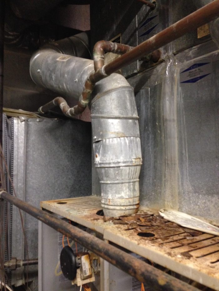
Now that I had to figure things out, I realized that the two air handlers were actually both feeding one big supply trunk (see Image #3, below). One big return connected to the intake on the bottom of one of the twins. Presumably, a hole had been cut in the opposite side to allow air to pass into the adjacent twin air handler’s intake.
It seemed that someone had decided they could create a 160,000 Btu/h furnace by taping two 80,000 Btu/h furnaces together. The side-by-side thermostats, then, were in one location because they were supposed to respond to the same conditions and activate the twin air handlers together!
Now that immediate replacement was an imperative, we set to work modeling the house to optimize the building envelope and determine loads. We designed retrofits for every part of the house to reduce our heating and cooling loads, but I had no idea how we would design a system that could meet our needs. The bizarre twin air handlers implied there was a single zone for the entire original 1954 house.
The sheer quantity of ductwork in the house was intimidating. Large basement bulkheads were packed with ducts. There were two supplies and two returns in all rooms with the exception of the small bathroom and smallest bedroom. It was nearly impossible to determine what was attached to what.
The first step was to do the old toilet-paper test just to figure out what was a supply and return (grilles and diffusers had been installed as if they were interchangeable), and if they were working at all. Once I mapped the location of all supplies and returns, I started drilling holes and cutting access into bulkheads to determine the layout of the duct system. Ultimately, I did enough exploration to determine how the ducts were configured — and sure enough, it was one big zone.
Understanding you have a problem
The house is at the high end of the street and has no shade trees. In the morning, the sun shines directly into six windows, including a large bank of four in the master bedroom. As the sun works its way around to the south, two more windows on the south side of the master continue to harvest solar gain. The south-side sunroom has a bank of large windows and a tile floor. In the late afternoon the living room and office heat up dramatically, thanks to the infamous wall of glass.
It was now March, and so the passive solar assets were playing in our favor. But in Baltimore, this 1970s passive solar dream for heating would become a cooling-demand nightmare.
Combined with no shade, virtually no insulation, stone walls, plentiful air infiltration, and stack effect through the vented attic, the house had all the attributes of a solar collector and a brick oven rolled into one delightful HVAC headache.
My goal, of course, was a right-sized, efficient system that would deliver comfort when and where it was needed, subject to all the changing conditions around the house over the course of the day. So our next task was to determine what zoning strategy could work with these asymmetrical load characteristics. We knew that we simply did not have the money to tear out the existing ductork and replace it all. We were going to have to work with what we had; but how do you zone a house with an existing single-zone duct system?
Our retrofit solution
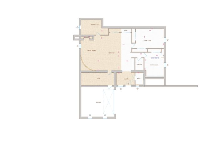
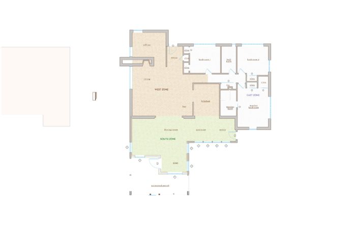
Our first step was to break out ideal zones by load profile, including solar loads and occupancy, while accounting for the planned retrofit yet to come. It was clear we had distinct east, west, and south zones by solar load profiles. It so happened that occupancy profiles roughly tracked with solar loads. We then overlaid the zone areas over the existing map of ductwork, supplies and returns.
We found that by cutting the main supply trunk at one, strategic location, we could transform the one-zone duct system into a two-zone system serving east and west zones (see Images #4 and #5, below).
A vertical chase leading from the supply trunk to the attic and back down to the sunroom on the south would be abandoned as undesirable (attic transit is not recommended) and largely ineffective (snaking flex ducts and high static pressure losses), and not in keeping with the zoning concept.
All of the southern zone would be served by a separate system to avoid going through or over the stone walls. With this scheme, the three zones would respond independently as the sun worked its way around the house in any season.
The remaining question was the lower level (a space formerly known as the basement). The lower level was finished but the bedrooms were not code-compliant due to the small well windows, which were of no use for egress, solar gain, or daylighting. We decided early on to make the bedrooms and recreation space of the lower level legal and livable by increasing the size of the windows. Still, the exposure to the earth as opposed to ambient temperatures (except on the walkout south side) and the limited solar gain meant that these spaces did not conform to our solar-load-driven zone analysis.
In addition, due to the ground contact, the basement maintains lower temperatures well into the late spring and would call for heat much longer than the rest of the house, particularly when the zones immediately above were being warmed by ample solar gain. During the cooling season, we feared that the upstairs east and west zones would drive over-cooling downstairs, which would presumably already stay cooler.
All of this conceptually argued for a fourth zone, though the duct layout made such an arrangement unworkable without abandoning existing supplies and adding new ducts. My assumptions of increased cost argued rather compellingly against this notion.
However, once we designed our envelope retrofit (we’ll discuss that in a future post), changed the size of the windows in the downstairs bedrooms and recreation space, and modeled it all in Wrightsoft for our Manual Js, and a zoned, dynamic simulation model in WUFI Passive, we found the lower rooms tracked more closely with the upstairs zones than expected, only with a lower volume of air.
In the heating season, solar exposure was less, but so were the envelope losses. In the cooling season, the added glazing definitely helped balance the equation, and the added insulation lessened the springtime losses to the ground, such that over-cooling appeared not to be a risk. We made the decision to do a central return in the open-plan recreation space downstairs to further encourage temperature equalization between the upper and lower levels.
So the decision was made to do a three-zone house: east, west, and south. The downstairs supply ducts were simply broken out and assigned zones roughly corresponding to the zones upstairs and according to the retrofitted split in the main supply trunk.
The systems
Our zoning concept and the existing ductwork drove equipment selection as well. Our retrofitted two-zone supply ducts, with large ducts, long runs and numerous branches, eliminated ducted minisplits from serious consideration. Mitsubishi was introducing a high-static-pressure, small, variable-speed air handler, but it was new and it lacked a tested zone damper system.
When I spelled out all of our objectives and the systems configurations, our HVAC contractor, Michael Bonsby Heating and Cooling, suggested that we look into the American Standard Platinum 20 variable-speed, zone-dampered system air-source heat pump. With our new load calculations, we determined that a 3-ton unit (down from 5 1/2 tons) would adequately condition both the east and west zones, even when loads were concurrent.
Once retrofitted, the south zone could be easily conditioned with a 1-ton wall-mounted minisplit, installed in what would be our superinsulated dining room. I was skeptical that this little unit could cool the solar-blasted sunroom space from one side of the building clear to the other, but the HVAC contractor was confident it would work.
Results
We have now lived through one winter, complete with a blizzard that left 28 inches of snow, plus a summer that saw a record-setting July and days in August and September well into the low 100s along with high humidity. I have to say the results have been pretty fantastic. The zoned, dampered American Standard has been very effective and a lot of fun to observe as it modulates total heating and cooling loads and air flow to each zone over the course of the day. Our hypothesis that zoning should be determined by solar gain is proving to be a useful approach.
During the heating season, the solar gains are concurrent with a virtually complete elimination of heating loads in the east and west zones in the morning and afternoon respectively. On cloudy days, which tend not to be the coldest, the loads are very evenly driven by heat loss through assemblies and the system evenly distributes heating to both zones with no problems. The system meets the peak loads we have experienced.
We do have a backup electric resistance coil. Prior to our insulation and air-sealing retrofit, it did kick in a fair bit, but less than I would have anticipated. There were only two comfort problems in the winter. One was that sitting near the 25-year-old Andersen double-pane windows before the sun came around was not very nice, which is another issue worthy of discussion in another post.
The other is that ground temperatures lead to a very cold downstairs, which lasted well after the ambient temperatures warmed up and the thermostat upstairs ceased calling for heat. But this was before any insulation improvements down below, and this effect should be substantially mitigated now that the envelope retrofit is underway. We will let you know next late winter and early spring.
Challenges on the cooling side
The cooling season has been a bit more of a challenge, driven as expected by solar gain. Our three zones show spikes in cooling loads following the sun’s transit around the over-glazed portions of the building. Generally speaking, the system has managed to keep up even on the roughest days, though localized increases in temperature do occur in the most exposed areas.
The master bedroom on the southeast corner of the house gets the brunt of the sun all the way through mid-afternoon. This room definitely experiences temperature increases of 3-7 degrees as the thermostat is located in the hall and does not respond to the localized demand. The good news is that we do not use that part of the house during those hours, so it is of little significance. On the other hand, a fan placed in the door to circulate hallway and master bedroom air equalizes the temperature fairly quickly.
The west side experiences something similar. In the afternoon the solar loads are so high that it inevitably heats up the space adjacent to the west wall. Ultimately the system keeps the spaces comfortable; they just have to run a lot more than I would like.
Of course, any good designer would understand these large energy demands could easily be lowered with shading. Indeed, a significant aspect of our retrofit plan entails shading for the east, south, and west windows with a combination of extended overhangs (south), sliding louver blinds salvaged from the German Embassy in Washington (east and west), and vegetation.
The impact of new shading was included in the energy modeling and load sizing, but remain to be executed. We anticipate these exterior improvements will virtually eliminate solar-driven gains, substantially reduce cooling loads, and eliminate our temperature increases under peak conditions, as well as reduce annual energy demand.
The central return has contributed to a reduction of stratification and thus far is working well, though we may have opted for more than one return and kept a small amount of return duct to decentralize the audible impact of the central return.
Hot stone stays hot
I’m confident we’ll have even greater success next year as insulation, air-sealing, and window work go forward. However, one sticky issue remains.
In the original stone house we have been limited in how much insulation we can add in a wall cavity of only 3 1/2 inches. When you combine the hot sun and the minimal insulation with the specific heat capacity of the stone wall, you really do feel the consequences.
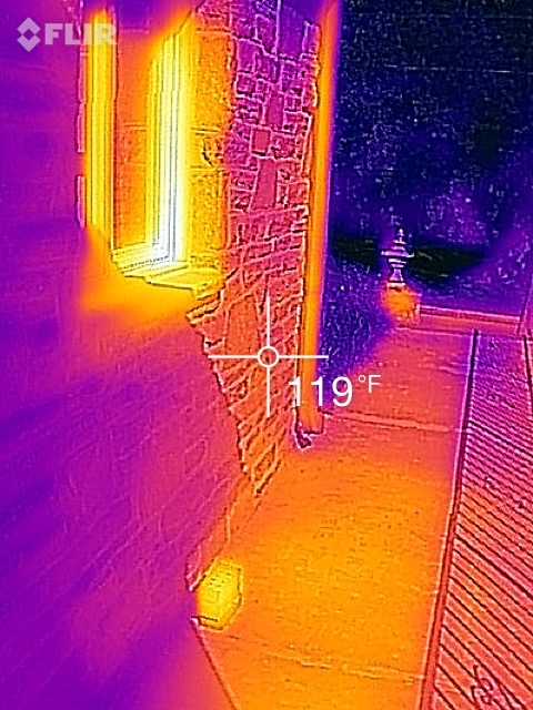
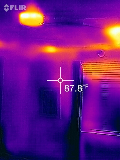
I have done a couple of days of thermal imaging (see the images at left). I will do a future post on this as well, but suffice it to say that the brick-oven analogy I used earlier is not that great an exaggeration. The surface of the stone is heating up to 120°F, and it is exposed to the sun long enough that I suspect this temperature is raising the whole mass of the stone to near that temperature.
The resulting comfort issue — and it is palpable — is the internal mean radiant surface temperatures we experience in the rooms with solar-loaded stone walls. What is particularly noticeable is how long the increase in the stone temperature impacts interior comfort. Well into the evening on the peak days of late summer, my face has felt flushed and slightly overheated when I walk into the bedroom, as if I’d been to the beach.
I have noticed this (though I have not tracked or monitored it) well after cooling loads have dropped in other parts of the house. The southeast corner continues to be baked by the stone, and cooling loads persist. On a cool evening this is not particularly problematic; we simply open up and let the breeze in. But in our area, we have many nights when the combination of warm outdoor temperatures and high relative humidity make that unrealistic.
This is maddening. I grew up in New England with windows open from April to October and no air conditioning, and I yearn to reduce carbon impacts wherever possible. I know in the shoulder months with heating loads and during the winter this mass will play to our advantage, but it still sticks in my craw. Mean radiant surface temperatures is, in my opinion, one of the more overlooked aspects of designing for comfort and low energy. We can say now with very direct experience what we knew in theory before: that radiant surface temperature can force you to alter your set point and operative air temperature to affect the same comfort outcomes at the expense of a significant increase in energy use and enviro-guilt.
In other words, shading the windows is only one aspect of mitigating solar gain. We will need to use our best passive design and amateur horticultural instincts to determine how to shade the house itself in the summer with vegetation and other design elements. This, of course, feels like another exciting design challenge and reinforcement of the holistic design idea that the building as a system acts in a truly integrated fashion with its site, and our interventions in any aspect of our property may well have an impact on our goals of carbon impact reduction.
Weekly Newsletter
Get building science and energy efficiency advice, plus special offers, in your inbox.


0 Comments
Log in or create an account to post a comment.
Sign up Log in