

Image Credit: David Goodyear
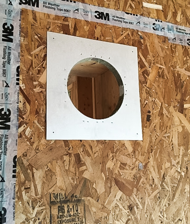
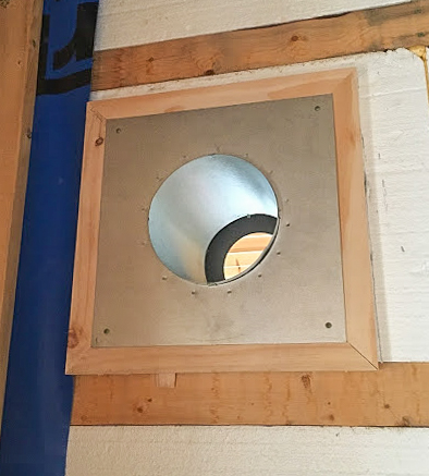
Image Credit: David Goodyear With the conduit pushed through the hole in the block, the fiberglass cavity insulation has been compressed against the back side of the OSB air barrier. Now, a 3/4-inch spade bit can be passed through the conduit and a hole drilled through the compressed fiberglass. Once the tip of the 3/4-inch bit emerges on the inside face of the OSB, the bit is withdrawn. From the inside of the wall, a 1 1/8-inch bit is bored through the OSB to accommodate the conduit. The electrical box is attached and ready for wiring. The electrical conduit is sealed to the interior face of the OSB air barrier with acoustical sealant and flashing tape. The rough-framed opening for the wood stove thimble as seen from the porch. After applying a bead of acoustical sealant to the perimeter of the opening, the author nailed the fire stop plate to the OSB. This is the view of the plate as seen from the interior. The thimble could be inserted into the framed opening with a decorative telescoping section on the inside. Gaps between the thimble and the rough opening were filled with fireproof insulation (mineral wool) before the fire stop plate was installed. The black section of decorative flue will be caulked to the galvanized plate when the stove is installed, making the assembly airtight. Installing the plumbing stack starts with drilling a hole through the top plate of the service wall and inserting the pipe into the attic. The 2-inch lines will be connected to a 3-inch vent in the attic that goes up through the roof on the north side of the house. Before installing the EPDM gasket, the author applies lots of acoustical sealant around the pipe and on the OSB where the gasket will sit. Flashing tape completes the installation.
More Guest Blogs


Editor’s Note: This is one of a series of blogs by David Goodyear describing the construction of his new home in Flatrock, Newfoundland, the first in the province built to the Passive House standard. The first installment of the GBA blog series was titled An Introduction to the Flatrock Passive House. For a list of Goodyear’s earlier blogs on this site, see the “Related Articles” sidebar below; you’ll find his complete blog here.
Dealing with penetrations in the air barrier has definitely been a source of stress during this project. Although my plans have the construction details, implementing them has pretty much been left to me. Some penetrations needed careful thought and planning to avoid compromising the integrity of the air barrier and fouling up the insulation in the wall cavity.
There are five wiring penetrations to the outside: three receptacles and two lights. Mounting the light/receptacle blocks to the exterior of the building could have been a mess if there was no foresight. It is hard to attach a trim block to a foam wall.
The only solution was to attach blocking to the studs directly behind the foam before the cavities were insulated. I used 2×6 lumber for that this purpose. Each block had to sit flush against the foam and had to be thick enough so that the siding would be just flush with the front of the block. I drilled a hole in each corner of the block and used 6-inch screws that went through the foam and into the blocking. Once the siding is finished and the electrical elements are installed, I will install a small plug in each hole. Without some thinking ahead, this would have caused a lot of headaches.
Conduit carries the wiring
Plans called for a piece of conduit to be routed through the exterior 2×8 wall and into the electrical box. The conduit would be sealed to the OSB air barrier on the interior with tape and acoustical sealant. Once the wire is routed through the conduit, the conduit will be filled with spray foam. The detail looked fine on paper. However, drilling through a wall with fiberglass insulation is an uncertain task; fiberglass has a bad habit of wrapping itself around anything that spins.
With than in mind, we came up with the following procedure:
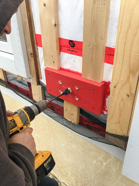
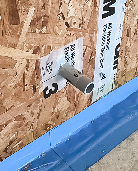
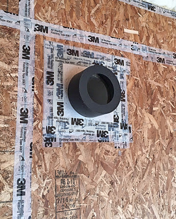
(1) Drill a 1 1/8-inch hole through the exterior block on the wall (see the image at the top of this page).
(2) Drill through the 3 inches of foam slowly until the bit breaches the back of the foam and the fiberglass insulation is visible.
(3) Insert the 3/4-inch conduit (1 1/8-inch outside diameter) from the outside and compress the insulation against the exterior side of the OSB. (My experience is that you can drill a hole through compressed insulation.)
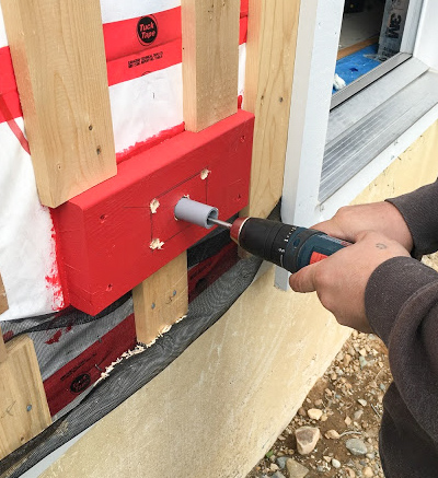
(4) Insert a long 3/4-inch spade it into the conduit and push it through until you feel the insulation at the end of the conduit (see Image #2 below).
(5) Drill until the tip of the spade bit just pierces the interior face of the OSB.
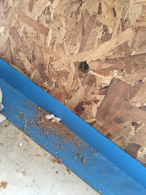
(6) From the interior, drill the piloted hole with a 1 1/8-inch spade bit until it just passes through the OSB (see Image #3 below).
After removing the conduit, I inspected the hole with a small flashlight. The insulation still filled the cavity — it hadn’t been disrupted by the drill. Although the hole was drilled with a 3/4-inch bit, there was enough give in the insulation that a 1 1/8-inch conduit easily passed through, as long as it was guided carefully.
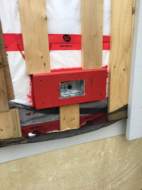
After drilling is complete, the opening for the receptacle is cut with a jig saw. (I used a hole saw for the octagonal boxes for exterior lights.) The conduit is glued to a 3/4-inch threaded section, passed through the electrical box and secured with a locking screw. The box/conduit assembly is the inserted into the opening in the trim block and secured with some screws (see Image #4 below).
On the inside, the conduit was caulked to the OSB with acoustical sealant. I made a tape gasket with 3M All Weather Flashing tape and pushed it into the acoustical sealant (see Image #5 below). The gasket was taped around the conduit for an airtight installation. Once the wiring is installed, the conduit will be filled with spray foam.
Flue for a wood stove
The original design for the house called for an interior stove pipe, mainly because interior flues stay warmer and warm chimneys perform better than cold ones.
After a fire has been lit, buoyant gases rise through the flue, raising the temperature inside the pipe. As the chimney gets warmer, this effect is more pronounced. A pressure differential is created between the stove air intake and the chimney that causes draft. Once a draft has been established it can be maintained by supplying heat. When compared to an interior installation, a chimney installed outside the building envelope needs more energy to establish and maintain an effective draft.
My internet searches really haven’t provided any hard numbers regarding the amount of extra energy required. Someday I may revisit this problem to see if there is some way to estimate the difference between the two scenarios.
Because of our floor plan, there was really one place to install the stove. But there were some uncertainties about the interior installation that I was not happy about. They included the spacing of the floor joists, the proximity to the bedroom upstairs, having to create a chase in the middle of one of the bedroom walls, running the air intake under the slab, and a lack of an airtight installation. It all added up to a complex problem that had a simple solution: Move the stove to an exterior wall.
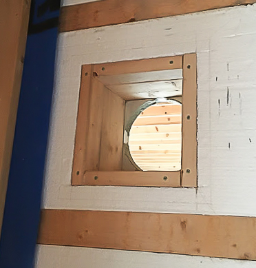
When passing through a combustible wall, a stove pipe requires a radiation shield (thimble). The options for an airtight stove thimble in our marketplace are few and far between. After some research, I found the Excel chimney made by ICC a Canadian manufacturer. The thimble required a framed opening of 10 inches square and can fit into a wall with a thickness of 12 inches or less. A decorative telescoping section can be used to ensure that the stove pipe exits the assembly 4 inches beyond the wall.
Combustion air will come from a 5-inch duct, equipped with a blast gate to close off air flow, that goes through the porch wall and terminates with a hood vent. After it emerges from the house, the stove pipe goes to a clean-out tee, then up through the porch attic and through the roof.
Photos #6 through #9 below show steps in the installation process.
Air-sealing the plumbing vents
Attics are cold in the winter and warm in the summer. Since they are vented through the soffit they are also drafty spaces. The attic could become an energy sink without lots of insulation and good air-sealing details.
Although we placed all the washrooms on one side of the house, it was pretty much impossible to tie everything into one main vent stack. The service cavity on the ceiling is 2×4 strapping on the flat so there just isn’t enough room to route each vent to a common place and tie them together before the vent goes into the attic. Instead, there are three individual stacks which are drilled up through the top plates in the exterior service wall.
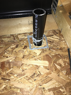
I knew there would be little distance between the edge of the pipe and the top plate of the exterior 2×8 wall. I needed to have enough OSB to tape/seal my gasket. My plumber, Melvin Way, drilled through the top plate of the exterior wall with a hole saw slightly bigger than the 2-inch pipe diameter. He kept the pipe as close to the inside edge of the plate as possible so there would be enough OSB in the attic to provide a surface to air-seal. He stubbed up through the attic with a vent that was about 12 inches high so I could slip the gasket down over the pipe (see Image #10 below).
When I air-sealed the ducts for my ERV and the air intake for the wood stove, I used Roflex gaskets from 475 High Performance Building Supply. They were pre-made and worked well. Since then, a friend of mine told me to make my own gaskets using EPDM liner made for backyard ponds. So I gave it a try. I cut the EPDM to about a 6-inch square, centered the gasket over the end of the pipe and used a utility knife to create a star shaped hole in the gasket using the pipe as a guide. The idea was to cut the hole so the gasket would fit snugly around the vent.
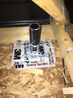
Using my trusty Ryobi battery-powered caulk gun (a tool I highly recommend), I dispensed a good bead of acoustical sealant both around the pipe and at the edge of where the gasket would lay on the ceiling (Image #11 below). I prefer Mulco Acoustik for air-sealing.
I pulled the gasket down over the pipe slowly, pressed it into the acoustical sealant, and then apply 3M 8067 tape around the edges. I used a J-roller to apply pressure to the taped surface to ensure adhesion. I finished the detail with 3M tape (see Image #12 below).
The 2-inch vents are connected to a 3-inch stack in the attic, which exists the roof on the north side of the house.
I think this is a redundant air-sealing system that is simple to implement and doesn’t require fancy materials. As much as I don’t like drilling holes in the air barrier, I’m pretty confident that these details will bring my air barrier back to Passive House airtightness.
Weekly Newsletter
Get building science and energy efficiency advice, plus special offers, in your inbox.


4 Comments
This is all interesting, but I'm really wondering how you finished this. How did you flash the electrical outlet, hose bib, etc at the siding and how did you trim it out?
bump
Potton,
If David doesn't see this and reply, you may find this guide useful:
https://hammerandhand.com/best-practices/manual/5-envelopes/5-1-wall-penetrations/
Thanks
Log in or create an account to post a comment.
Sign up Log in