

More Guest Blogs


Editor’s Note: Lyndon Than is a professional engineer and Certified Passive House Consultant who took a year off from work to design and build a home with his wife Phi in North York, a district of Toronto, Ontario. This is the first in a series of posts about the project, beginning with the start of construction in early 2012. Than describes the process in his blog, Passive House Toronto.
We began designing a Passive House for our residential lot in north-central Toronto in January 2010. I had come across the concept of Passive House building online and began explaining to my wife that even here, in Toronto, we could have a house with a heat load so low it wouldn’t need a furnace or a boiler. She surprised me by saying, “Yes — let’s just do it that way.” It was 2009, and the Passive House movement was still in its early years in North America, but we decided to pursue it.
I was not a seasoned builder or building scientist. My past construction experience included a garage, a kitchen, and working as a project manager on a larger residential building, but I’d never undertaken a project like this one. Neither did we have enough money — only about half of what we thought we’d need. But armed with the optimism of ignorance and excitement, we believed it could be done.
The garage on the property would stay, but the bungalow would be removed completely. We needed a house with two floors and a basement, with a maximum footprint (due to zoning restrictions) of 1,585 square feet. I bought the software, and started analyzing the concept.
By the time I’d jumped into the first Toronto training offered by the Passive House Institute U.S. (PHIUS). I already had an idea of how much insulation we would need, and how thick the exterior walls would have to be. But the building I had designed was ugly. I had never designed much more than my garage. We took the design to five architects to get their feedback. They helped so much, and they had the tact to let us down gently.
My wife and I hated each other at times during design! We disagreed on so much — the deepest attachments we have in life are to ideas, and our spouses are not the ones to tiptoe gracefully around them. But by October 2011, after starting from scratch again, we had the final design, and we were ready to move ahead.
First, demolish the bungalow and salvage some of the materials
As we neared the start date for construction, we moved out of the bungalow, disconnected electricity, gas, water, and phone services, and salvaged what we could from the existing building. That included every ounce of fiberglass insulation. After all, it was only 60 years old.
We had to build window and door bucks, and prepare the detached garage as an on-site workshop and office. On January 10, 2012, the bungalow came down. In the week that followed we demolished the building and removed 35 truckloads of soil and two bins of debris from the site.
The 1,523-square-foot footprint of the new house would be just 500 square feet larger than the bungalow it replaced, but with a basement that is 12 inches deeper. The excavator crushed the building into the basement until everything was in small pieces, and scooped it out into 40-cubic-yard bins in the space of three days. This first phase was standard, but it’s expensive to remove soil.
Terraprobe, an environmental engineering and construction company, performed a soil verification test just an hour after the final excavation with the entire pit open. (The three-page report cost $450 plus tax.) Tests showed the glacial till was more than strong enough to support the design loads of the new house.
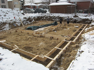
At the end of the week, surveyors came to drive in 3/8-inch pins to mark the corners of the building. Since we would be making very precise footings (I’ll explain why shortly), we used a laser level and built the footing forms ourselves.
Forming and pouring the footings
It was cold. We worked in temperatures ranging from -10°C to -5°C (14°F to 23°F). One day it was -17°C (1°F) with the wind-chill. Thirty bales of straw kept the earth in the pit from freezing. We added another eight bales later. Working down there one could tell the how cold the earth was. To our surprise, the side of the excavation close to the neighbor’s house was noticeably warmer (due to the heat loss from their foundation).
It took extra time to build the footing forms because their placement had to be exact. We did the work ourselves; the wall-to-footings intersection had been carefully designed. Basement walls would be in line with the outside edge of the footings, so the forms had to be executed precisely along these outer edges.
The forms for the outside faces of the footings would stay in place after the footing pour. Made from 2x12s, the forms were anchored to the footings with Zamac T-35 female anchors spaced every 8 feet. Because I planned to rest the wall forms directly on top of the footing forms, the forms had to be in the right place, and also very solid.
We also formed a key at the outer edge in the footing to hold the walls against earth pressures, and also to improve water sealing. Initially, there would be no concrete floor slab to hold the walls in place, as there would be with more conventional basement foundation structures. The footings were made to be like grade beams.
The concrete contractors were pretty leery of this process, but they agreed to our style, and by the end of it, I think they were pretty happy with the process. Referring to me, and the way I asked them do things, they said it was “pretty good — for a shoemaker.”
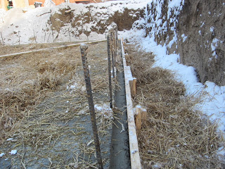
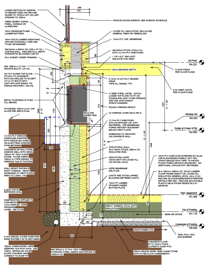
Much later, the floor slab would be placed between the footings rather than on top of them. This, plus the deep footings (11 1/2 inches deep), would allow us to place insulation under a wood basement subfloor while the basement floor joists rested on the footings. (See the section drawing below, Image #5).
We seemed to have done a good job forming the footings, because there were absolutely no issues in placing the 10-foot-high wall forms later. This process seems like an ideal way to form lot-line footings. I also feel that drainage of water down along the basement wall is improved by having the footing and foundation wall edges in line. The water easily bypasses the seam between wall and footing and it can flow right down to the weeping tile. We used higher-strength (25 MPa) concrete all around to improve watertightness.
Weeping tile will be placed on both sides of the footings. Inside, the tile will drain to a deep sump pit in what will become an elevator shaft. Drainage of the basement is of utmost importance since the airtightness requirements will mean a raised subfloor will be needed in the basement, as far as we can figure out for now. And we don’t want any water under this floor.
Pouring the foundation walls
It took a crew of eight a full day to place all of the 10-foot forms for the foundation walls, place the ties, the rebar and window bucks, straighten and brace the forms, and place the scaffolding. (That seemed super fast when compared to how long it had taken us to build forms for the footings.)
The next morning, they oil-sprayed the forms, did some final straightening and bracing, and poured all of the concrete (4 1/2 truckloads totaling 36 cubic meters) in three hours.
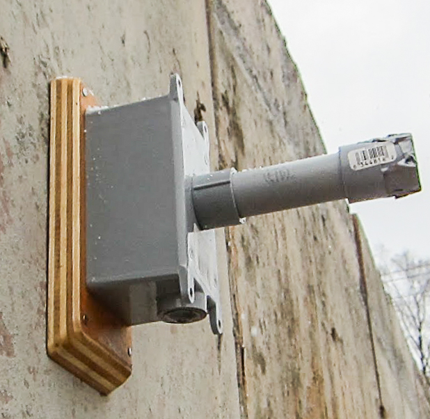
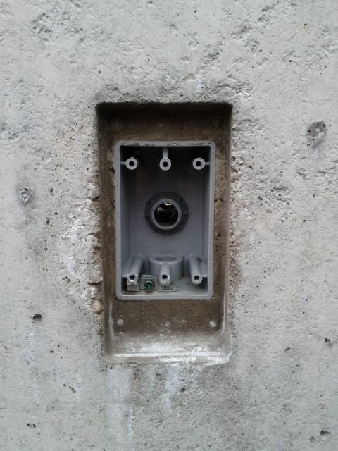
We cast outside electrical outlets into the walls. I looked long and hard for plastic boxes designed for casting in place. I did find them (Kwikon is one brand), but they had to be ordered and they weren’t cheap. Normally, contractors use what are called “slab-boxes.” They’re cheap, but in my opinion not very good. So I came up with my own way to cast boxes into the concrete.
We started with a simple outdoor PVC box and mounted it to an oiled wood plate with PVC conduit fixed to the back of the box. The wood plate was mounted to the concrete forms with small nails (see image # below). It’s a good idea to make the total length of the conduit and box about 1/4 inch less than the thickness of the wall to avoid complaints from the concrete crew . Make sure to move the concrete around the boxes completely so there is no honeycombing or voids. Materials for each box cost about $7.
A novel approach to foundation walls
We had people go by our site and wonder why we were doing things backward. Normally, one builds concrete walls and places a wood floor system on top of them. We didn’t. The wooden house frame rests on the concrete footings, not on top of the foundation walls. Why? One thing we’re discovering about radically energy efficient buildings is the structure!
When a structure is not designed for insulation it gets very hard to achieve thermal-bridge-free construction. Placing the first wood (or steel, or whatever) floor frames on top of the concrete walls means there is a strong connection to the concrete, but the concrete is a heat conductor, not an insulator. Unless the concrete is on the warm side of insulation, this is a significant thermal issue.
In this design, the structural concrete is on the cold side of the insulation. This means the outside shell of the building is hard. When one thinks about a building lasting 25 years, having rigid foam on the outside might seem OK. But what if we want it to last 150 years or more? Well, I don’t know if that will happen with this house, but it seems a good idea to have the outside shell be hard and durable.
One loses some potential to have thermal mass inside, but that can be achieved in other ways. With the wood frame placed this way, we have thermal separation between the inner frame of the house (which is the structural frame) all the way from the footings, up to the roof. Therefore, framing starts in the basement, not on top of the concrete foundation walls. This might seem like a radical departure from conventional practice. But so far, in our project, we’ve found no real problem.
There are some consequences, however. First, we start with wooden walls, not floors. If we started with floors, the insulation inside them would get all wet. So we wait for the roof to be on and the building closed up before building the basement floors. This also reduces the natural settling of the building — most of the shrinkage of framing lumber happens in the floor frames. Although the wide footings are very level, we also shimmed the walls so they are not in contact with the concrete and any water can drain from under the walls, into the space between the footings, and finally to the sump pit.
The framed walls against the concrete are not sheathed. Again, this is so we can insulate the space behind the frames after the building is closed in. We borrow shear (racking) strength from the concrete walls to stabilize these open frames. The photo below (see Image #6) shows a wide 3/4-inch plywood top plate (placed over the upper top plate), which reaches to the concrete and laterally anchors the walls to the concrete with steel brackets. The 1/2-inch Zamac anchors ($1 each) were placed in the forms during the wall pour, but could probably be drilled in afterwards. The concrete crew didn’t really pay attention to the location of these anchors so you’ll see that some of the steel brackets connect to the underside of the plywood, and some to the upper side.
Keep the insulation inside the building
I’m not a fan of “outsulation“ (placing the insulation on the outside of the building) as I find it creates all sorts of problems for exterior cladding, and the vapor profile is not as good. Keep in mind we are talking about houses in the Canadian climate—and trying to achieve high performance. It just gets silly when we have 8 to 10 inches of insulation on the outside of the building.
The two-wall system I used simplifies much in this regard, and allows the cheapest, simplest insulation to be employed. Insulating concrete forms certainly simplifies much as well, but there are drawbacks. The concrete core lends nothing to insulation value and takes up space.
ICFs also rely heavily on oil-based materials (foam), and there is often little to no verification of how well the concrete has been poured. Cracks and the like are hidden not only from view but from water, so leaks are difficult to find. Attaching cladding is hard when insulation is located on the outside of the building. There are ways of dealing with this — such as Spyder Tie, TF Forming Systems, and Nudura One — but they seem expensive.
Weekly Newsletter
Get building science and energy efficiency advice, plus special offers, in your inbox.


6 Comments
Moisture accumulation in the basement wall insulation?
Lyndon,
Looking at your basement wall detail, it's clear that your concrete wall will stay quite cold during the winter. You have chosen to install "batt or loose-fill fiberglass or mineral wool" on the interior side of this cold concrete wall. Are you worried about moisture accumulation at this interface -- where the fluffy insulation touches the cold concrete? I would be worried.
.
The red dashed line... @ Martin
The red dashed line is half-inch CDX detailed as an air barrier and coaded with a liquid applied vapor retarder. That's probably going to be sufficient to prevent moisture accumulation from wintertime moisture drives, but has very limited relief of any ground moisture that finds it's way into the concrete. With sufficient above-grade exposure on the concrete that might be OK too.
I don't see any capillary breaks between the footing & foundation wall, nor any under the footing, only a perimeter drain & damp proofing on the exterior side of the concrete, so there is a real potential for ground moisture wicking into the wall via the footing.
https://www.greenbuildingadvisor.com/sites/default/files/Than%20foundation%20dwg.jpg
They have done more than I
They have done more than I have since I'm still in the planning phase.
I've been planning to have insulation both inside and outside. Mostly I want to avoid the concrete from experiencing any freeze/thaw cycles. I thought that would help avoid cracks.
@Dorsett.
Lower right-hand side of the drawing indicate 10 mil poly under slab. Perhaps it terminates at the delta membrane on the wall portion?
Cold Concrete Wall
Hi All, Thanks for the insightful comments.
The cold concrete may be a bit of a concern, but I've been observing it for a few years now and I don't see any issues as yet......though basement insulation is not quite finished in some parts, so there is some opportunity to compare also.
The placement of concrete on the outside of the wall is typical of foundations in Canada (and I suspect in many parts of the US). Our codes have recently (10 years ago) increased the required basement wall insulation levels from R13 to R20, so code regulators are moving towards colder and colder concrete walls as well. In our case, the design calls for about R50 on the inside of basement concrete walls. This perhaps leaves the wall colder than code-built walls might be, but certainly, even the code-built walls are below typical dew-point temperatures. I agree with D Dorsett - moisture drive in wintertime will be minimal with the interior vapour barrier/air tightness.
Moisture wicking up from the ground into the concrete: well, the delta MS is only on the side of the wall, and the poly under the floor slab does not extend under footings. Our only defence is that we used 25 MPA concrete - not necessarily very high, but does have higher cement content - the higher strength concretes are more water resistant, less porous. I would say then the the main contact with water would be on the base of the footings - a fairly long distance from grade, at 7' away - where freeze-thaw damage is getting to be more of a concern. Of course, we can have freeze somewhat lower down - like 4' down in a deep freeze - still 3' away from footing bases....so we would need both a deep freeze and very wet conditions deeper down driving moisture into the concrete....I'll spec poly under footings next time.
On the interior, we have place dimpled membrane against the concrete, so there is a separation from fuzzy insulation up to about 5' from footings. In addition, we've placed the wood wall on blocks, so any moisture does have a path out to the concrete slab.
LT
Stunning work
I think it would be more impressive if you can apply the universe LED RGB light as well.
Log in or create an account to post a comment.
Sign up Log in