Comparing thermal bridging between envelopes.
Reading through this informative thread on the “Significance of Thermal Bridging”, I wonder if there is simpler way to estimate thermal bridging through a “rough analysis”?
Though I’m sure there are times when it is worth modelling actual heat loss through thermal bridging, in many cases it seems as though it should be enough to say “thermal bridging is not good”.
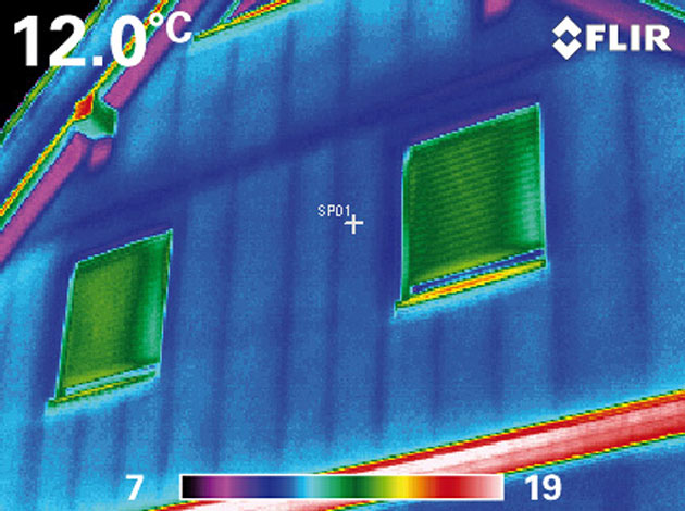
A “rough analysis” that excludes framing factors and whole wall R values focuses strictly on which parts of the structure provide a continous path from one side of the envelope to the other. For the purposes of a “rough analysis” I propose to “think” like a thermal imaging camrea.
Here is what I am thinking:
I think of a “thermal bridge” as a type of thermal “short circuit” from the conditioned side of the envelope to the exterior.
Thinking like a thermal imaging camera, I “see” all the framing members that make a continous path from the inside of the envelope to the outside.
Still thinking like a camera, I add up the cross sectional area of each thermal “short” that I “see”. I can use this information to compare that envelope to what I “see” in another envelope.
In fact, I wouldn’t even bother to add up the areas, but just do a more qualitative comparison.
Or maybe this is what many people already do…
Examples posted below.
GBA Detail Library
A collection of one thousand construction details organized by climate and house part


Replies
In the following examples, I painted red on the exterior portions of the framing members that make a continous path from one side of the envelope to the other. Comparing the total area of red painted on each wall indicates that the truss wall has only ~6% of the thermal bridging of the standard 2x6 wall.
It would be even less than that.
Unlike electrical short circuits, thermal shorts create much more of an energy path when they're literally short, because the outward flow volume is dependent on both the length and the aspect ratio (edge to side area). Unlike electricity, heat moves in 3 dimensions through and out of a "conductor".
So, to finesse your rough calculations, you might take the exposed area ratio and multiple that by the bridge effectiveness (edge to side) ratio.
Thinking like a thermal camera is cool, but I prefer to think like a mountain.
A "Mooney wall" example:
I see.
So, if I'm still thinking like a camera, the effect of aspect ratio would be to modulate the brightness of "shorts" that I "see"?
Sometimes speaking in metaphor is "cumbersome".
And I agree that "thinking like a mountain" is best.
ARGHHH...
What your illustration shows is a simple cross-hatch wall, that's been in used at least since the 70s, mostly for renovation projects (I used it in 1982 on a gut rehab in Boston). It's mentioned in super-insulation books published in the 80's.
The "Mooney Wall" is one variation on this framing system that uses insulweb glued to the strapping, and dense-pack. But Tim Mooney doesn't deserve credit for inventing the cross-hatched method of increasing insulation cavity depth and reducing thermal bridging.
That's why I used "quotation marks".
Will reconsider future use of "mooney wall".