
Image Credit: Daniel Morrison
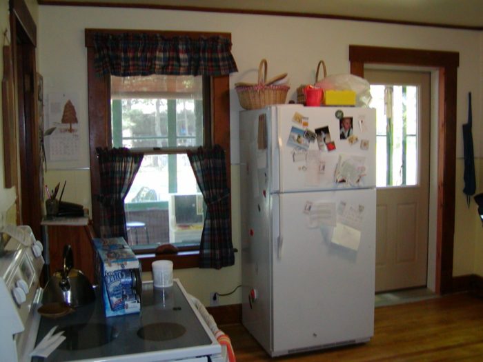
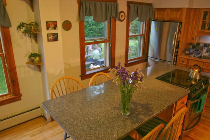
Image Credit: Peter Yost The existing 12 by 12 foot kitchen has four doorways and three large windows. The stove and refrigerator locations were not planned; the appliances "ended up" in each space. This is looking at the west wall of the kitchen with the porch visible through the kitchen door and window.
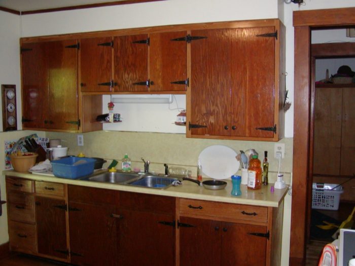
Image Credit: Peter Yost On the east wall of the kitchen, the sink countertop space is the ONLY countertop in the entire kitchen.
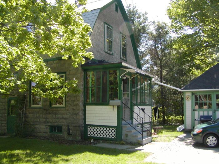
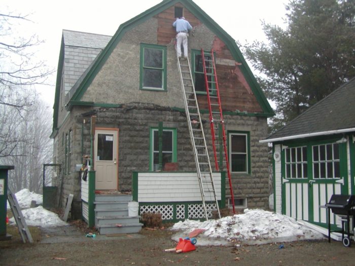
Image Credit: Peter Yost The kitchen addition started with demo of the back porch and the 2nd floor gable exterior (failing stucco and lathe). Note the new kitchen back door; this door was purchased for swing and hinge setup for the new kitchen addition back door but installed temporarily inside and out backwards in the existing kitchen.
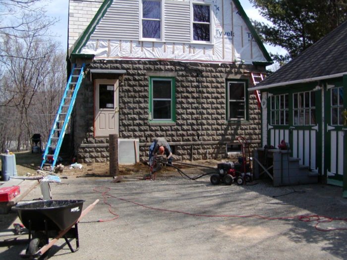
Image Credit: Peter Yost Sono-tube piers extending below the frost line make up the SIPS kitchen addition foundation. The SIPS floor/pier foundation was selected to minimize use of concrete and to make it easy for weekend warriors to get the foundation done.
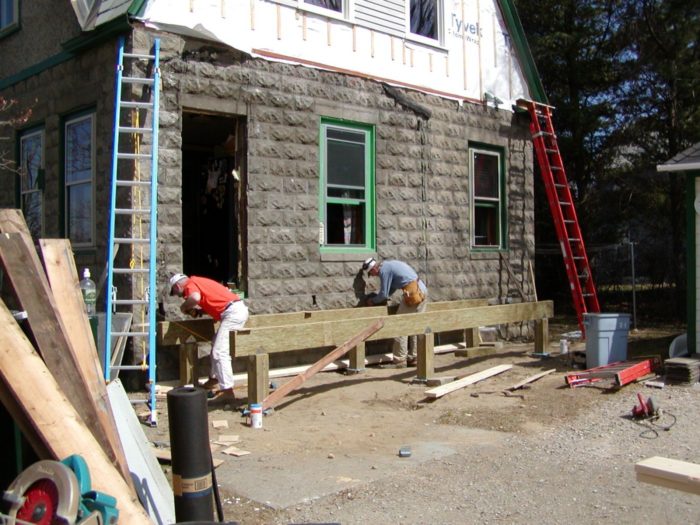
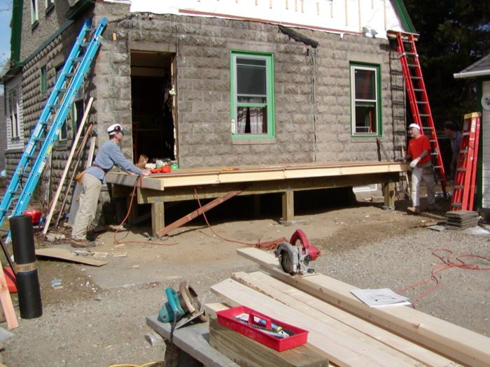
Image Credit: Peter Yost Pressure-treated Parallam beams are installed on the PT posts, which are rebar-cored to the concrete piers. Note the blue capillary break membrane just under the posts, isolating the concrete from the wood in the assembly.
Image Credit: Peter Yost Using retired climbing gear to cinch the SIPS floor panels firmly together. And a big sigh of relief as the floor panels line up perfectly with respect to the the existing kitchen's floor assembly.
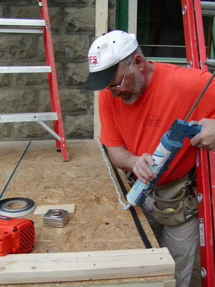
Image Credit: Peter Yost A rubber gasket, two beads of sealant, and then later an interior bead of sealant form the air seal detail where the SIPS floor meet the SIPS wall panels. It's a belt-and-suspenders and then some approach to address the Achille's Heel of SIPS assemblies: air sealing panel joints.
Image Credit: Peter Yost 3+ carpenters (Hey, I was mostly taking pictures...) installed all of the SIPS panels in less than a day, including the roof panels without a crane or lull.
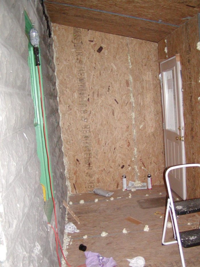
Image Credit: Peter Yost The dollops of spray foam prove that the keyhole channel cored into every Winter Panel SIP joint is air sealed. You drill holes through the interior plywood spline then spray foam insulation into one hole until spray foam expands out the adjacent hole. You can also see the spray foam where the floor and wall SIPs meet the existing split-faced concrete block.
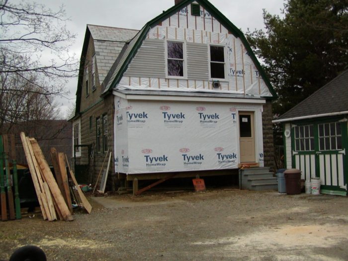
Image Credit: Peter Yost The SIPS addition was weathertight in about a day and a half from foundation to roof membrane and wall housewrap.
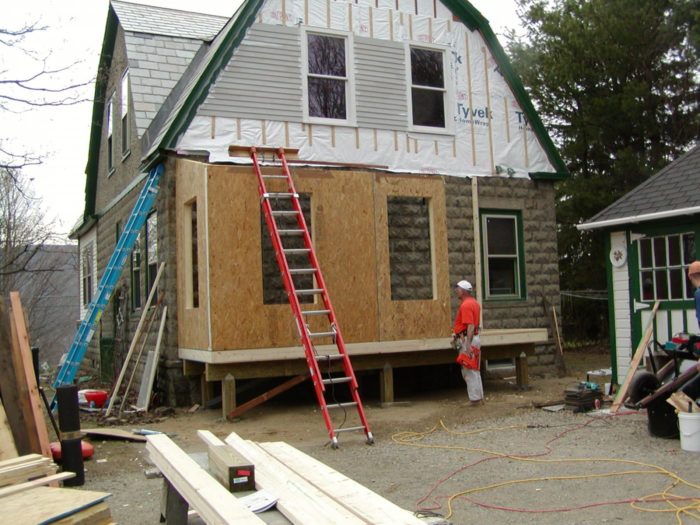
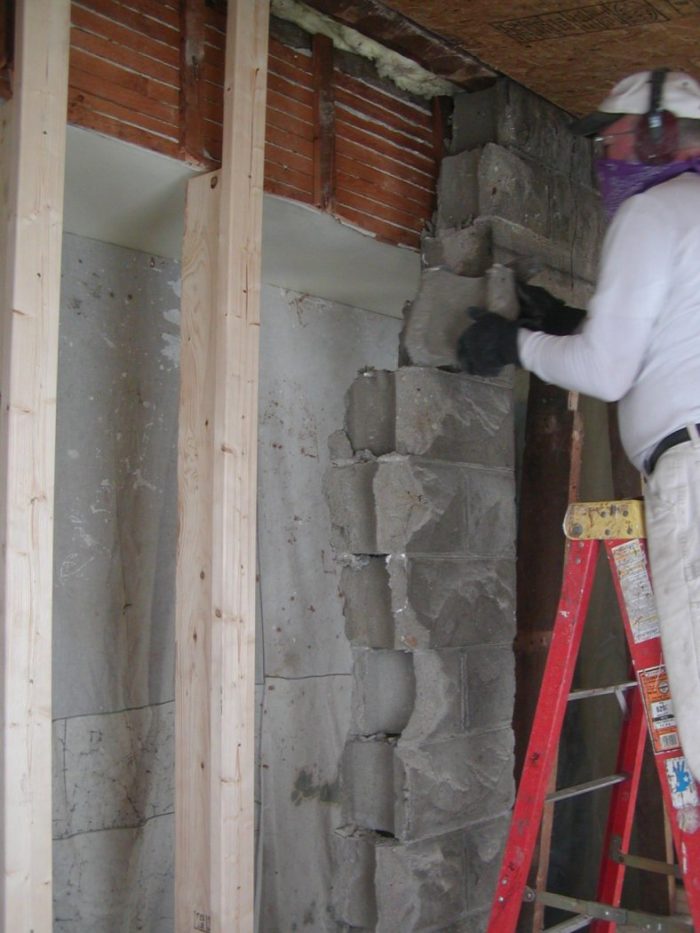
Image Credit: Peter Yost With the SIP addition weathertight, demolition of the west wall concrete block in the existing kitchen is done, block by block.
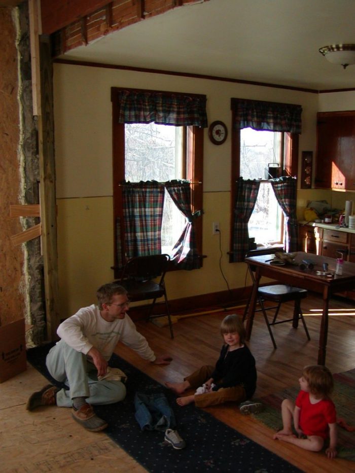
Image Credit: Peter Yost With the old kitchen wall down, the girls explore the new space and the renovation crew takes a break. Each phase of the project was carefully timed to accommodate the office "day jobs" of the crew and the family schedule.
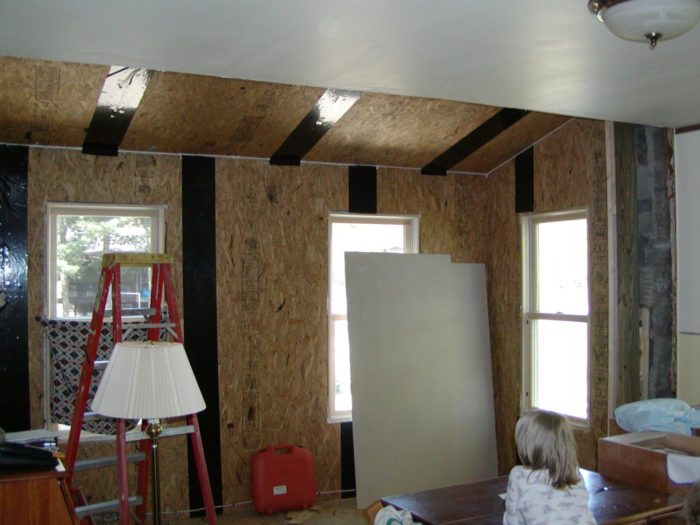
Image Credit: Peter Yost Ready for gypsum board. Note the final interior sealant at the roof-wall joint and the membrane strips at each panel joint.
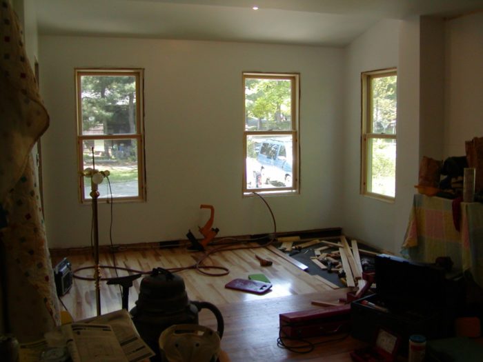
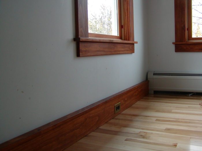
Image Credit: Peter Yost Pre-finished red birch flooring matches the existing kitchen floor well. We pretty much had to run the new flooring perpendicular to the existing to span the block wall section at the old wall plane.
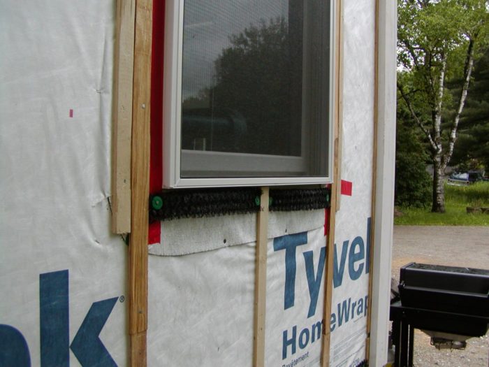
Image Credit: Peter Yost Both the window opening and the window unit are flashed. With the very low drying potential of the SIP panels, it's really important to back-vent the cladding installation (furring strips used here) to maximize the drying potential of the assembly to the exterior.
Image Credit: Peter Yost All the kitchen wiring (outlets, interior lighting, exterior lighting) was carefully planned to avoid any routing of the SIPs, including this baseboard raceway.
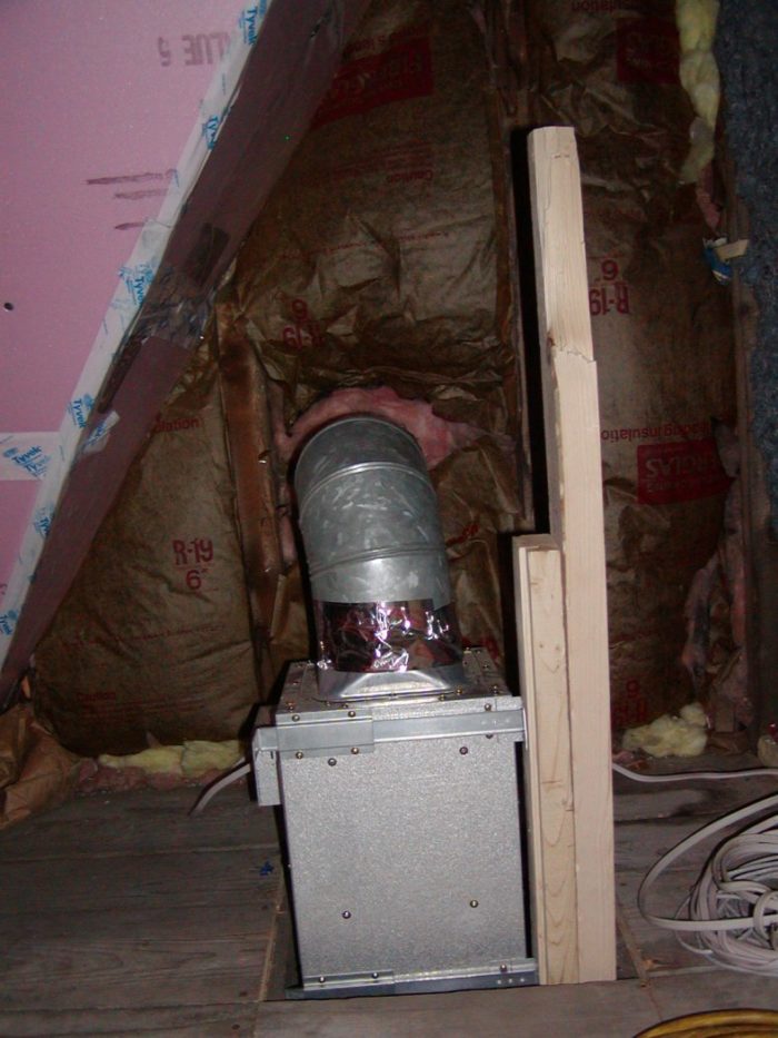
Image Credit: Peter Yost During renovation of the west bedroom just above the kitchen, access to the knee wall space was planned to accommodate subsequent installation of the high performance kitchen exhaust fan.
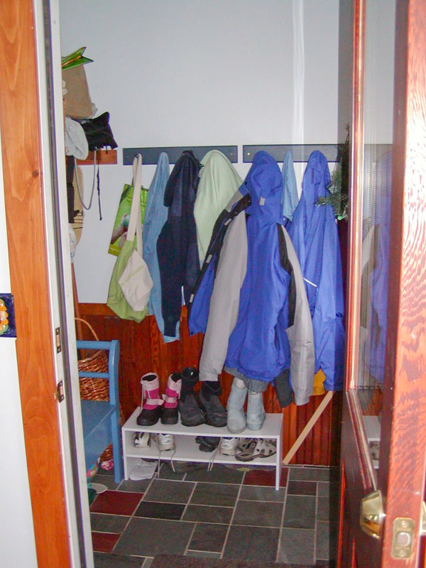
Image Credit: Peter Yost The weatherlock mudroom just off the kitchen addition is just about a New England necessity.
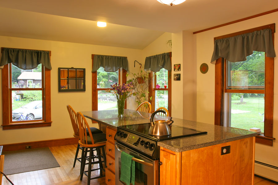
Image Credit: Peter Yost **A multitasking island** The long central island has room for cooking and entertaining.
Image Credit: Daniel Morrison **A little space can go a long way** The SIP addition extends the kitchen only about six feet, but results in a spacious room.
Image Credit: Daniel Morrison The dimensions of the kitchen addition were designed to a two-foot module to minimize SIP cut-off and cut-out waste, integrate with existing roof rake details, and to accommodate a 5 by 5.5 foot mudroom as part of the addition.
Image Credit: Steve Baczek
Converting a back porch to living space makes a cramped kitchen roomy — and adds a mudroom to boot
Old houses didn’t need big kitchens because they weren’t the central gathering spot that today’s kitchens are. The 12-ft. by 12-ft. kitchen in the house my wife, Chris, and I bought ten years ago was just such a space: small and dark. It was pretty typical for a 100-year-old New England home, but it was challenging for how a kitchen works in the 21st century.
We needed more space, more natural light, and better placement of the workstations, but the four doors and three windows limited our options. The most logical approach to designing a more functional kitchen was to expand out the back side of the house, but what would the configuration be? It was really helpful to work with architect Steve Baczek, who provided us with about six different options for the locations of major stations: sink, stove, refrigerator, dining, food prep. Interestingly, the layout that looked best involved the least reworking of major systems: space heating, electrical, and plumbing.
Choosing a building system
I have to admit something here: I am a member in good standing of both the Recovering Remodelers Association and the Wannabe Building Scientist Society. I want our home to be cost-effective, safe, and energy-efficient, but if I get to use new techniques, new tools, or new materials, I probably can’t resist “experimenting.” And I need projects that I can do largely on my own and that are staged according to lots of weekend and vacation work.
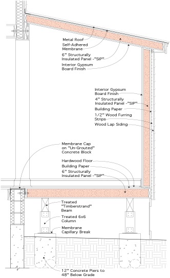
I had never built with structural insulated panels (SIP) before, and the kitchen/mudroom addition seemed like a perfect fit with a pier foundation I could do on my own. I knew that the toughest part of SIP construction is air sealing the panel joints, so I went with our local Winter Panel system because I like the panel joint detail the best and because the company manufactures polyiso foam panels, the highest R-per-inch on the market.
Resource efficient by design
Perhaps the trickiest part of this project was working out the dimensions to fit the existing west wall configuration and to minimize SIP cutoff waste. We pushed the addition just as far as we could to the south, right up against the downstairs bathroom window. This meant a pretty tight mudroom (6×6 outside dimensions), but it made the overall length exactly 18 ft., a 2-ft. module. In terms of the width, we had to honor the distance to the detached garage and make sure that the shed roof of the addition could still tuck under the existing rake of the west gable on the north end. It turns out that a 6-ft. width gave us the 2-ft. module on the floor, walls, and roof panels with a 4-in-12 pitch. It would be really tight at the north corner of the addition at the existing rake, but we double-checked this several times and even did a rough mock-up to ensure we had the room. We also ended up with less gypsum board cutoff waste on the interior.
The new home center
Our family has gone from avoiding the kitchen to living in it. The new space is great not only for cooking and dining, but also for homework and family game night. The large island draws the new and old spaces together, and the mudroom is a great weatherlock all year round. Although the kitchen addition and other work on our home have expanded the conditioned space by about 20%, our energy bills continue to decline each time we tackle yet another high-performance renovation.
Weekly Newsletter
Get building science and energy efficiency advice, plus special offers, in your inbox.
Lessons Learned
An R-38 floor is still cold
The heat loss from the R-38 SIP floor in the addition is no greater than the heat loss from the R-38 walls and roof. The only problem is that we don't walk on the walls and roof. When we step from the kitchen floor over the basement to the kitchen floor of the addition in the middle of winter, the 5+ degree surface temperature drop is more than a bit uncomfortable in a home with a no-shoes-inside policy. Just as soon as I can get the lumber stock off the racks I built under the kitchen addition, I will be adding another layer of polyiso rigid insulation to the underside of the kitchen addition floor.
Too many windows
In the kitchen (and the front home office, for that matter), we went with large double-hung windows (2.5 by 5) in the addition, with a pattern that matches the existing kitchen window layout. That adds up to 25% of the total exterior wall area of the kitchen, and it is simply too much. We love the way the banks of windows make the kitchen feel, but the heat loss in winter and solar gain (especially to the west) in summer is a feel we like a lot less.
If we had it to do over again, we would take out at least one if not both of the west wall kitchen addition windows. On the other hand, maybe really high-performance window treatments for both heat loss and solar gain will be available soon and give us the best of both worlds.
General Specs and Team
| Location: | Brattleboro, VT |
|---|---|
| Living Space: | 250 |
| Cost: | 70 |
| Additional Notes: | The original kitchen was 144 sq. ft.; the addition is 72 sq. ft. of kitchen space and 36 sq. ft. of mudroom. The approximately $18,000 cost of the kitchen addition/renovation does not include the author's labor or the appliances (stovetop, oven, refrigerator). |
Construction crew: Christian Yost, Tom Henze, Ron Benson, Dave Gauthier (Winter Panel), Peter Yost Roofing: Walker & Sons, Hinsdale, N.H.
Construction
Foundation: Concrete piers, Parallam beams
Floor, walls, roof: 6.5-in. SIPs
Wall cladding: Back-vented, factory-primed, finger-jointed cedar lap siding
Roof cladding: Galvalume standing seam metal roofing
Windows: Marvin Integrity double-hung metal-clad wood
Energy
Refrigerator: Energy Star Amana (bottom freezer)
Energy Specs
Windows: U-factor = 0.32; SHGC = 0.28; VT = 0.48
Floor, walls, roof: R-38 polyisocyanurate foam
Water Efficiency
Kitchen faucet: Brizo SmartTouch electronic touch/motion sensor activation
Dishwasher: Energy Star Frigidaire
Indoor Air Quality
- 150-cfm high-performance Fantech exhaust fan
Green Materials and Resource Efficiency
- Pier foundation
- Salvaged maple trim
- Kitchen cabinets reused in garage and basement
- Kitchen sink donated to ReNew Salvage for resale
- Existing stove reused in family apartment complex
- Locally quarried and finished granite countertop


13 Comments
Opinion of SIPS?
What is your current opinion of SIPS after using them? Are they all that some claim them to be? What was the approximate premium over traditional wood framing?
Would you use them again?
SIPs opinion
Yes, I would absolutely use them again. Are they the only way to build a high performance wall or roof assembly? No, but they do the job, go up fast, and if detailed right at the joints, are really air tight. Treat them with respect in terms of moisture management techniques, and you have a durable system, as well.
Nice
1.)How much SIP panel pre-machining did the SIP panel mfg. provide.
2.) Did you have to leave some cutting/machining of SIPs for the field in order to ensure accurate fit with the existing structure?
3.)Did you do much SIP foam scooping with hot wire?
4.)Was angled foam scooping involved such as for the top inlet nailer for the wall at its junction with the roof? If so, from what mfg. did you get the hot wire equipment from?
5.) How did you double bevel rip inlet nailers? (such as for the junction already mentioned). For example, what sort of table saw set up did you have to ensure good rips along the entire length of inlet nailer?
My interest in your project has a lot to do with your week-end warrior approach.
Sorry for the book of questions--maybe you can answer without too much work, maybe not.
Rick's SIP questions
1. Panel pre-matching: piece of cake--all the panels are done on Auto-CAD and then labeled/numbered for easy assembly.
2. Did NO cutting or machining--these panels snicked together like LEGOs. Couple of tricks related to the plywood splines, but nothing fancy or requiring any special tools.
3. We planned all of the wiring for the addition so that we did NO routing for electrical, but the baseboard raceway was the key. See the photo gallery.
4. same as above--no routing for electrical
5. All of the panels are routed for the edge two-bys at the plant. There were no double bevels. Nothing special about my table saw, but for the longer plates it took two guys at the table saw.
Take a look at the Winter Panel installation manual; you can dowload it from their website. The same architect who did all of our GBA details did the Winter Panel details. And I was the principal author, along with Dave Gauthier--Winter Panel President--for the manual.
Peter....
ahhh.......ok........thanks?
Peter and Rick...
1. So the mfr routed everything but you had to install nailers and bucks for windows, doors, edges...?
2. With enough to play with, couldn't a compass-tracing of the stone profile be made onto and cut into the SIPS that meet the wall, recess your nailer, and seal it up?
3&4.Is a wire/scoop necessary if the mfr had not routed? Can you dado or router? --probably overkill, but perhaps more common (at least in my shop)
5. maybe I'm missing something from the question or the drawing, but the boards in the detail drawing look like simple cuts using a fence and angled blade, flip the board as necessary to avoid wedging the acute edge under your fence, and make the second cut parallel. Could be done with a circular saw and fence, too.
6. (bonus question) In the "lessons learned" section, are you concerned about sandwiching the outer layer of SIP with a layer of polyiso under the addition? The attention to drying details at the wall assembly make me scratch my head about this crawlspace retrofit. I'm not the expert here, but I would be careful about sealing the edges and around supports to encapsulate the SIP and create a new vapor barrier. Or am I being paranoid?
some info about some of your Marshall's sip questions
Marshall,
1. I believe Peter answered "yes" to this question. However, his project was somewhat simple. It is not uncommon to need to cut SIPs and rout foam in the field (or scoop it out with a hot wire knife)
For 3&4: I made a mistake in my questioning when I asked about hot wire scooping of foam. I had forgotten that Peter's project involved polyiso foam sip cores. That foam is typically ROUTED to accept the embedded boards (called inlet nailers by Murus and splines by Winter Panel). Hot knives with wire shaped in the form of the cross section of the inlet nailers or splines are usually only used for scooping out the foam in SIPS with EPS (expanded polystyrene) foam cores.
For 5: The boards (inlet nailers or splines) are typically 2x dimension lumber that sometimes need to be ripped on a bevel or double bevel. SIP core thicknesses are made the same as standard 2x dimension lumber, such as 2x6, 2x8, 2x10. However, when the edges of the inlet nailers need to be beveled, you need to go up a size with the rough board stock, because of the angle.
Rick and Marshall follow-up
Rick is right all around, except on one point:
1. bucking windows: Winter Panel gives the option to rout out or not around window perimeters. You don't really need the the bucks there if you are willing to use trim screws to attach everything around the window perimeter (including attaching the window, albeit not with trim screws). Why rout out that high performance expensive foam unless you need to?
2. compass tracing around split-faced block: I could have, but this would have been really time consuming, probably made squaring up the panels more difficult, and really had no real advantage for air tightness because we foamed these areas and infra-red imaging shows we did fine.
3. added layer of foam on underside of addition: good question. Since the added foam is about conductive heat loss and not air tightness, I am not that concerned about how well I need to fit the foam around supports. And since the polyiso core of the panels is already VERY low in vapor permeability, I am not concerned about reducing drying potential to the outside. I am most concerned about bulk water and flashing if I have a low drying potential, and on the underside of this addition, there is really no bulk water wetting potential. Lastly, you referred to the addition as a crawlspace; remember this was a pier addition.
A few things
The Winter Panel Installation guide is available in the FURTHER RESOURCES section of our [**SIPs page**](node/623) (as well as a bunch of good info on SIPs, IMHO).
I would think that routing around the stone would be WORSE for a few reasons, harder to square up the panels (as Pete pointed out), worse thermal performance, because you'd have an irregular edge, which means routing foam for the nailer would be more difficult to get exactly right, and it would take longer.
Great article! I appreciate
Great article! I appreciate reading about smart, progressive, 'family budget comes first' projects that aren't gold-plated 100k bathrooms like lots of articles out there. The staging of the weekend warriors is especially nice to see; that brings a whole new layer of coordination and complexity yet it is the way lots of us have to function on small-to midsized-projects especially nowadays.
Ledger attachment & header design.
I'm curious about the ledger attachments. Any problems setting the anchor bolts into hollow cmu's?
What kind of header did you use where the cmu's were removed?
Thanks for your time,
T Wilson
Ledger attachment and header design
You are right; lagging into hollow CMU's is largely wishful thinking. But note that we did TWO carrying beams on piers so the ledger was more of a "keeper" (completely foamed in place around the lags) than a load-bearing ledger. If I had to make this ledger load-bearing, I would have grouted the cores as part of securing the lag bolts.
The header I used was a Microllam LVL beam. Since this was a gable end, the block was not really carrying much of a load but I was adding the shed addition roof load to the gable. My memory tells me that it was a 1 3/4 by 11 1/4 inch member, more than enough for the load; we erred on the larger side since I had plenty of room for the depth of this beam.
Lessons Learned and R-value: Thanks for the great article, Peter. With the benefit of hindsight, you probably would have ordered SIPs with higher R-value. What R-value would you have wanted? And what SIP thickness would that have been?
Log in or create an account to post a comment.
Sign up Log in