
At my firm, Birdsmouth Design-Build in Portland, OR, builders and architects ask regularly if we can help them design high-performance assemblies that are well-above code, approachable for the average builder, and cost-effective for clients. The question seems eminently solvable, but on further inspection can prove tricky. Expanding this question to cover most climate zones in North America makes things even fuzzier. When GBA approached me to share a couple of our go-to details for the Expert Exchange program, my mind went straight to this conundrum. How do we share details that can be useful to broad swaths of people when there are so many variables to consider beyond climate zone including budget, availability of materials, and local trade knowledge, to name a few?
One thing that remains consistent no matter the conditions is the importance of getting the four control layers right. All our assemblies integrate strategies to control bulk water, air movement, vapor drive, and thermal losses—in that order.
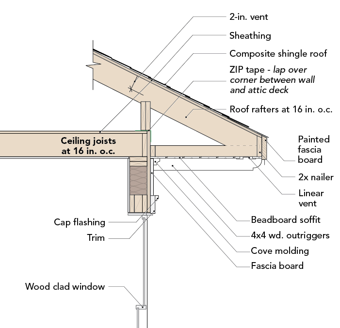
For the purposes of this article—part one of two—I will assume most readers are fairly versed in controlling bulk water. I’ll jump to the next layer in line of importance: the air barrier. In most homes, the leakiest parts of the building are the top plate-to-roof connection followed by the bottom plate-to-foundation connection. Focusing on these two areas seems beneficial to the greatest number of people. I will share how our firm approached the detailing of these two locations on a new home we are building in Damascus, OR, climate zone 4C. Here, I will address the foundation-to-wall connection. In my next post, I will talk about the wall-to-roof connection.
A little backstory
Both assemblies are taken from a certified Passive House build. When designing and building to best practices, our firm uses the Phius 2021…
Weekly Newsletter
Get building science and energy efficiency advice, plus special offers, in your inbox.

This article is only available to GBA Prime Members
Sign up for a free trial and get instant access to this article as well as GBA’s complete library of premium articles and construction details.
Start Free TrialAlready a member? Log in


10 Comments
Hey Josh, nice to see the evolution of this design.
I know PT foundations are controversial for most, have you looked into any design possibilities using this type of foundation system. My father built several structures, both residential and commercial using pressure treated wood for the foundations with success before I got into the industry. Early in my career, he and I built a couple homes with them. All the structures still appear to be solid; some are more than 40 years old.
I've also been toying with the idea of a frost protected shallow foundation system for the concrete-free slab design. Probably more relevant in my climate where our stem walls are 5 feet deep.
Looking forward to part 2.
Hi Randy,
We recently had a client that was in a PT wood foundation here in the city of Portland. We went down the path for a little bit in schematic, but ultimately decided against it not because we thought it wasn't a robust foundation (it is allowed in the IRC), but rather it was far enough afield from typical construction that it was a pretty good premium for not just the construction, but also the design (and specifically, the design review at the planning department). We didn't feel like locking horns with all the trades, building departments, inspectors, etc. for this particular project. That being said, I do find the idea fascinating and know there are numerous examples of successful wood foundations that are 100+ years old and going strong. If the right project comes along, we are game to give it a go...
I'd love to see you riff off of this idea further and incorporate a frost protected shallow foundation. I can't think of any reason why it wouldn't work. Make it happen and let me know so I can follow along!
Cheers,
Josh
Josh,
It looks like a really well thought out detail. I wonder if a couple of small variations might make it simpler?
If y0u didn't notch and let-in the foam on the stem wall, but rather moved the wall framing in so that the sill plate overhung the inside of the wall instead, it would do two things:
- Cover the bottom of the exterior wood fibre insulation, meaning you could eliminate the base flashing and mesh protection, except for a small piece necessary for the bottom of the rain-screen gap. This should also make the sills at exterior doors easier to support.
- Move the sub-slab insulation up so the top was flush with the stem wall, and run it under the cantilevered sill plate. To regain the height you lost, and make installing baseboard trim easier, you might then want to add a second sill plate.
Hi Malcom,
First off, thanks for the tip that helped us evolve this foundation in the first place. Since then we have further discussed and refined the idea. It's one of the great benefits of this forum.
Your detail is similar to one we had considered early on. One of the issues we ran into with shifting the plate to the interior is one reached a point where one can't go beyond a certain point. Specifically, the holddowns and to a lesser extend the anchor bolts need to be located no less than 2" from the edge of the face of the stem wall. This is per our engineer. We use 6" stem walls here in the PNW, so this limitation gets in the way. That being said, I realize that other parts of the country use thicker stem walls and one may be able to shift this plate in further (we could do this too, but we are trying to avoid the carbon and costs of concrete in the first place). In parts of the country that aren't in seismic zones this may be even less of an issue.
I could see using a wider bottom plate, especially since it will plane out with the 1.5" of plywood you have shown in your detail. A potential issue with this approach though would be the min 1/2" gap needed for the expansion and contraction of the floating plywood slab would be moved more to the interior. With the right finished floor this gap may be bridged just fine (a floating engineered floor, for instance).
This all boils down to creativity and modifying the approach to fit the particular circumstance at hand. For one, we have realized that the CCF SOG foundation isn't great on sloped sites due to the amount of gravel that needs to be trucked in to 'fill' the foundation to the correct grade. In these cases, we are exploring conditioned crawls.
Thanks for the detail and I will continue to mull it around!
Josh
Josh,
I'm indebted to people like you, Mike Maines, Ben Bogie and others who think up and try these innovative assemblies. For more risk-adverse people like me it's great to be able to benefit from your more creative approach.
Josh,
Not to nitpick the THERM model, it does show the general behavior, but it's missing a the foundation anchor bolts. Those essentially inject that purple area up into the bottom of the wall / sill plate where the temperature gradient is already very high. I would be curios to see how adding a ~ 1' long 5/8" cylinder of steel in the middle of that curved the isotemperature surfaces change the behavior, assuming you've still got all the inputs and setup mostly ready to go. Maybe it's not all that much?
Is it valid to do a 2d analysis at the anchor bolts, given that the heat flows are actually 3d and the anchor bolts are infrequent? Not to say that the anchor bolts don't matter, but I'm not sure that a 2d analysis at the anchor bolts would actually give you a meaningful surface temperature at the interior surface.
Brendan,
It's an approximation to be sure, but a 2D model (rectangle) of the diameter of the bolt would show whether or not there was a significant impact "in the plane of the bolt". In the line between anchors, I imagine it would look more like the diagram looks now. What I'm curious about is the 'cold spots' created along the bottom of the wall, and whether or not any of the surfaces near the interior drywall fall below the dew-point of the interior. In his climate zone, it might be unlikely, or not happen often enough to matter.
In the interior states, where the temperature is more, seasonal, it could have a larger impact.
If the 2d model at the bolt does not show any condensation risk at the interior drywall, you can be confident that there isn't a risk.
But what I'm curious about is that if the 2d model at the bolt does show a condensation risk at the drywall, would that risk still be there if you ran a 3d model? I certainly don't know, and I don't think there is free software available to run a 3d model like that. I'd be surprised if it caused a real-world issue, but again, wild speculation on my part! It'd be interesting to know.
To follow up and add to this conversation, the bolts were not included in the THERM model. We had Phius do this work for us and they didn't ask for this information. I tend to agree with kbentley57 in that I doubt the impact of the vertical bolts spaced at 4' will make much of an impact. Certainly not to the overall energy usage of the home.
It is important to note that this THERM model was done for climate zone 4C. I would trust this would work for all zones 4 and less, but I would strongly suggest running a model in colder climate zones as I suspect one will be required to use an exterior insulation at the stem wall to avoid cold spots and condensation at this location.
Log in or become a member to post a comment.
Sign up Log in