
More Guest Blogs


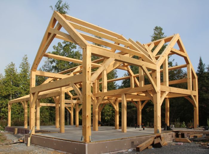
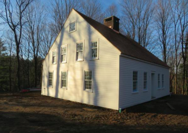
Rob Myers is building a timber-frame house in Ontario, Canada, at a site on the Bonnechere River an hour and a half west of Ottawa. This is the first installment of a blog series.
I have been intrigued with timber-frame building since reading a Ted Benson book many years ago, so when the opportunity to build a new house presented itself, I decided that it was time to give it a try.
I am not a professional builder, so in preparation I took a course at Gibson Timber Frames in Perth, Ontario, and then a second course at Fox Maple School of Traditional Building in Maine. (Both courses are highly recommended.) I then spent the next year and a half designing the timber frame itself and choosing the building systems that would be used. My main goal was to learn a bit, enjoy the process, and have fun.
A timber frame is built with longevity in mind and I felt that the other systems selected should be consistent with this goal. I live in Climate Zone 6 (bordering on 7), so obviously airtightness and good thermal performance are important. But I also feel that a house is not a series of abstract specifications and numbers, but rather a place that you live in. It is a balance between functionality, beauty, and heart. In this particular build, I was leaning more to the heart side.
The footprint of the frame is about 1,250 square feet and the cathedral ceiling height is about 19 1/2 feet. This blog describes the solution I found for a very specific problem: how to enclose the timber frame with an energy-efficient shell (without breaking the bank).
Choosing the shell
There are a number of good design approaches for walls and roofs that achieve excellent energy performance. This made choosing the enclosure one of the most difficult and time-consuming aspects of the design.
The timber frame itself also complicated the decision. For example, it is the nature of a timber-frame building to have high cathedral ceilings, so packing insulation into an attic or truss system is not an option. It is also worth noting that for owner-built homes, the cost of materials is usually more important than the cost of labor. Thus, a system that simply minimizes labor may not be the best bargain for an owner-builder. And so I waded into the choices….
Infill panels or an exterior shell?
I first had to decide whether to use an infill system (where the walls are built between the timber posts) or an external shell that enclosed the complete frame. Infill is fussy work, difficult to air-seal, and difficult to add services to, and since I also wanted to fully expose the frame on the inside of the building, the best choice for me was an external shell.
For the shell, I looked at a number of different wall construction systems before narrowing the choice to four different approaches (for four quite different reasons): SIPs, wood chip/clay, standard 2×6 with exterior foam, and Larsen trusses with dense-packed cellulose.
Initially, my first choice was to use SIPs: They have a history of use on timber frames and many people in the field told me that this was the easiest system to use, which is probably true. The construction is very fast and it is possible to get panels that have drywall already installed.
However, as I worked through the design there were several things that I found problematic. The material cost is high and it is necessary to hire a crew and a crane to erect the panels. It is of course possible to do the work yourself, but you then lose the primary advantage, which is speed. I also did not like the idea of a system that depended on absolutely perfect installation technique, especially since many seams are blocked by timbers, making it fairly difficult to achieve this level of perfection.
Running electrical and plumbing can be more difficult in a SIP house. And in order to use a cold roof design (which I believe is necessary in a cold climate), you still have to build a second roof — which again offsets any speed or cost advantage.
I bounced back and forth between my choices and was not convinced that any were ideal. I was about ready to look seriously at SIPs again when I came across an article by Thorsten Chlupp on the REMOTE (“Residential Exterior Membrane Outside-insulation Technique”) wall system that he was using. His design made total sense to me, and for this project I felt that it was the perfect wall system.
The REMOTE system
I consider the REMOTE system to be one of the most elegant solutions to building a robust, high-performance structure in a very cold climate. There are several very good references for REMOTE building, most of which were published by Thorsten Chlupp and The Cold Climate Research Center in Alaska.
In many respects, there is now little difference between a REMOTE wall and an advanced 2×6 wall with exterior insulation: the two systems seem to have converged. I think that when the same solution is arrived at from two different directions, then it is probably a good solution.
I am not an expert, but to me the main difference between these two systems is the placement of the air/water control layer and the amount of outer insulation used. In a REMOTE wall, the air control layer is placed in the middle of the wall, and although this seems like a minor change, it makes a big difference in terms of ease of construction and the future integrity of the building system. In my view, one of the major advantages of the REMOTE system is that you can easily air-seal the shell. And once you are finished there is no danger that future work (such as plumbing, electrical, or drywall work) will undo all of the careful air sealing.
The REMOTE system also takes to heart the idea of continuous control layers and it avoids the problems with sealing a wall-roof junction.
The basic steps for my project were: build a box around the timber frame, air/water seal it, and then add exterior insulation to completely cover the box. Eaves and rakes overhangs are then “floated” on top of the foam, resulting in zero thermal bridging. Finally, insulation is added to the wall cavities. In my case, the end result was a very tight building with an R-42 wall and R-61 roof.
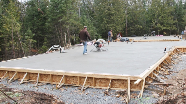
A thickened-edge slab
The floating slab was a standard thickened-edge design with 3 inches of 30 psi XPS foam underneath.
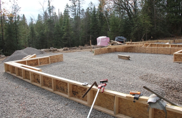
The site is a limestone outcrop that drains in three directions. (It is pretty much at bedrock.) The area for the house and shop was cleared and leveled, and then 6 inches of 3/4-inch crushed stone was spread, leveled, and compacted. The site built forms were simply set on top of this gravel. (I later re-used the material from the forms.)
The biggest problem was trying to anchor the forms, since stakes could not be driven very deep, if at all. I did the best I could and they held reasonably well. During the pour the sides actually lifted slightly (which was not anticipated), so when the forms were removed I had to remove and re-attach the rigid foam in some areas.

The plumbing drain pipes were installed at three levels: beneath the slab, in the slab, and above the slab. This photo (right) shows the main drain which runs under the slab and the insulation.
Slabs are not all that common here, and one of the things that I couldn’t seem to find information about was how to set the toilet flange. A simple solution is to run a 4-inch pipe and use a 4×3 toilet flange, the outside of which conveniently fits inside the 4-inch pipe. After the concrete is placed, the pipe is cut flush with the concrete (or the finished floor) and then the flange is simply glued in. This is probably common knowledge for many plumbers (but not for me).
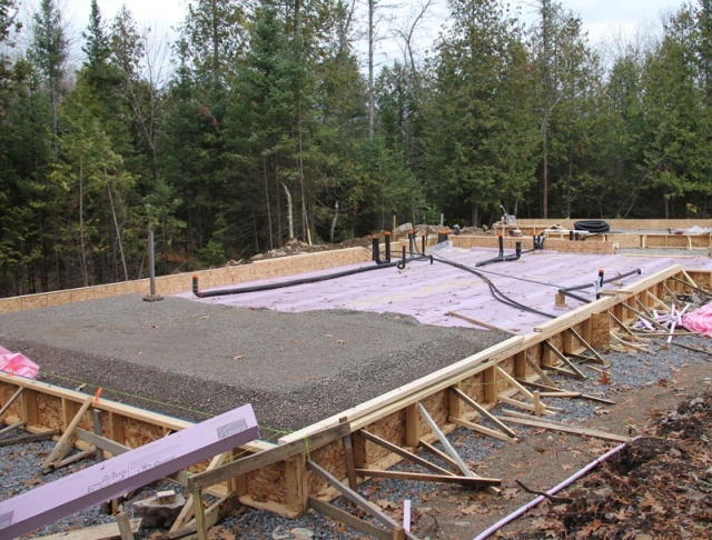
In the photo at right, the 3-inch-thick rigid foam has been installed on the gravel base and the plumbing lines and service pipes have been set. Clear 1/2-inch minus crushed stone was used to form the thickened edges of the slab and set the thickness of the center area. This gravel was compacted in 3-inch lifts.
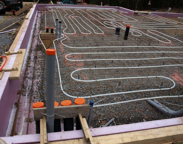
Two courses of 5/8-inch rebar were added to the bottom of the thickened edge portion of the foundation, and 6″x6″ wire mesh was used to reinforce the top. PEX tubing for radiant heat was tied to the top of the mesh, and then the mesh was raised using 2-inch plastic chairs. (The PEX is thus near the middle of the 5″ thickness of the slab.)
I don’t expect to use a radiant heating system, but it was inexpensive to add the PEX tubing, and the tubing is there if I need it. The 2-by wood strips that are visible at the edges are there to form a ledge in the concrete so that the exterior door sill can be set flush with the slab surface. (This also helps with sealing the sill against water intrusion).
The finished floor will be acid-stained concrete, so the concrete is the actual finished floor height.

Concrete is fairly permanent. Ideally, everything will go as planned for the pour. Unfortunately, there were several moments of excitement during our job, including delays in scheduling, very cold weather, late arrival of the concrete pump (and the ensuing lineup of several anxious concrete trucks with loads of heated, accelerated concrete), feeding concrete too fast from the pump and almost blowing out the forms, and finally, equipment failures during finishing. However, we had a skilled crew and it all worked out.
As soon as the slab was finished, I spread hay over the surface to about 4 inches thick and then covered it with black poly (hoping for any thermal gain we might get from the sun during the day). The temperature at night was below freezing and it snowed heavily the next day. But when the plastic was removed in the spring, the slab was fine. Interestingly, the hay left a beautiful line pattern etched on the concrete surface; I’m hoping that the lines telegraph through and are still visible when acid stain is applied.
Vertical rigid foam at the perimeter of the slab
For the edge of the slab I used high-density type rigid foam which was inserted vertically inside the forms before the concrete was poured. The rigid foam tended to stick to the concrete when the forms were removed, and the foam makes it easier to strip the forms.
After removing the forms, I drilled holes 16 inches on center through each piece of rigid foam and into the concrete and used 5-inch Tapcon-style fasteners with Wind-Devil plastic washers to secure the foam to the concrete. (Ultimately, the foam is also held in place by backfill).
Using high-density rigid foam on the edge was definitely overkill, and it created a few problems. When driving the screws, I couldn’t compress the foam enough to sink the washers (without stripping the concrete screw or distorting the washer), so I had to use a hole saw to cut 1/8-inch deep rings that allowed the washer to be countersunk. I sprayed low-expansion foam into the depression formed by the washer, and after it cured, it was cut flush using an oscillating tool with a foam-cutting blade (basically a wide razor-type blade).
I sanded lightly after cutting, but it is not a good idea to try to sand without first cutting the foam flush — spray foam is too soft and is impossible to sand flat. Also, although any foam-style cup washer will work, the advantage of the Wind-Devil is that the screw head is sunken into the washer and when the foam is applied it then allows a small thermal break over the screw head.
The exterior of the foam was then finished with an EIFS waterproofing material (I used Durex Ectoflex) that is rolled onto a nylon mesh tacked on over the rigid foam. The system was easy to use (mixed as needed, it sets by drying and has a several hour pot life) and it appears to be pretty tough — a good strong kick with a steel-toed work boot won’t mark it, but it will make for a sore ankle. (Don’t ask how I know this, but it’s not a recommended way to test the coating). If desired, a colored top coat can be applied, but I didn’t bother.
Installing the sill
I thought that the air seal between the slab and the sill was going to be problematic, but there was a simple solution: I just used an EPDM gasket available from Conservation Technology. Once the gasket is compressed by the sill plate, it is watertight and airtight. In fact, the seal was so good that it actually caused problems during construction. I installed the sill plates early to prevent scaffolding from rolling off the slab while erecting the timber frame, and the seal was so tight that the slab filled with water every time it rained. I finally had to cut and lift parts of the sill to allow the slab to drain.
I like to use redundant systems, so the sill plate is also air and water sealed using metal flashing with pest-block foam applied to the sill as the flashing was set. This ensures that the wall’s water control layer directs water past the outer slab insulation. The flashing also serves to protect the underside of the wall foam that overhangs the slab insulation.
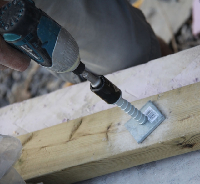
I used Simpson Titen HD bolts to secure the pressure-treated sill plates to the concrete slab because this makes it easier to finish the concrete. (No bolts sticking up during the pour.) It also makes the sills much easier to install accurately, since they can be laid exactly in place and then drilled.
As explained later, the sills had to be spaced 5/8 inch out from the timber frame in order to later install drywall, so accuracy was important. As a side note: although instructions for drilling concrete often use the terms “hammer drill” and “rotary hammer drill” interchangeably, these are not the same beast at all. You can save a lot of time and aggravation by renting or buying a rotary hammer drill. (I found a smaller Bosch rotary hammer drill on sale for under $100 Canadian).
Rob Myers has worked as an analytical chemist, high-tech manager, and purveyor of fiery foods, all of which served to support a lifelong love of woodworking and building (not to mention a wicked tool habit). He is currently on a (possibly permanent) sabbatical from any real job while he builds an off-grid timber-frame home near Eganville, Ontario.
Weekly Newsletter
Get building science and energy efficiency advice, plus special offers, in your inbox.


9 Comments
Radiant backup
I'm curious about the Pex that you may not use. You are just installing it in case you've underestimated your heating needs?
Radiant Backup
Ethan,
I previously installed a radiant system in a shop that I built and I really liked it. In this particular house we are heating with a high-efficiency wood stove and it can easily supply enough heat - but as anyone who heats with wood knows, the heat is not necessarily in the right place. I have never lived in a house with concrete floors and I was concerned about comfort levels in the bedrooms.
The house is designed for heat circulation by natural convection but I felt that for the cost of a few feet of pex and a days work it was worth putting a radiant system into the slab. If the bedroom floor feels cold when it's -30 degrees, it will be nice to have an easy way of dealing with it. The pex is zoned so that I can add supplemental heat to only the guest bedroom/bathroom or the master bedroom/bathroom if necessary.
Insulation approach
Rob,
You mention that the REMOTE strategy is the one you are using, but I'm confused, because the system you describe actually sounds more like the PERSIST method. (It's benefit is simple air, vapor sealing at the roof/wall intersection. Please correct me if I'm wrong, but I believe the REMOTE system uses a raised heel truss to insulate the roof (with insulation inwards of the exterior sheathing). This isn't possible with timber frame, but the PERSIST method is. (It (PERSIST) happens to be the strategy I'm currently using on my build NH (Zone 6A).)
Can you elaborate more on how you are using the REMOTE strategy on your timber frame? Do you have other pics, details, etc., that you could share with me via email?
By the way, your project looks great!
Insulation Approach
Brad,
As I mentioned, I am not an expert but you are certainly correct in saying that the building is similar to PERSIST. The method I used was closest to that described in a 2 part video from the Cold Climate Research Institute and most of the references for the design were from work by Thorsten Chlupp, so I used their acronym. REMOTE is of course based on PERSIST, the main difference seems to be that PERSIST uses vapour impermeable membranes and usually does not use interior insulation. Perhaps someone with more knowledge could comment, but it appears that the early REMOTE buildings more closely resembled PERSIST and then (as described in the REMOTE Manual) later used the raised heel truss and switched to dense pack cellulose. As you noted, I couldn't use a raised heel truss so I modified the design (based on the REMOTE design principles) and in doing so may have made the building closer to PERSIST. And now I feel acronymed to a stupor....
The building method will be described in more detail in a later BLOG but if you have any specific questions then I would be happy to answer them if I can. And thanks for the compliment on the project.
So far so good.
I look forward to some reports of your plans for energy since the house is off grid. And by the way, Thorsten Chlupp also uses insulated closing window shutters. (I do too). Any plans for that? If well done they make a tremendous difference.
Insulation Approach
Rob,
Thanks for the response. I'm no expert either!
I waded through many of the same decisions and spent hundreds of hours researching the various approaches too, when I stumbled upon an article that described the PERSIST method, I was immediately struck with its obvious benefits. The CCRC videos, research, and manuals have all been excellent, especially the 10 year studies/findings they did on walls. Combined with what I knew about PERSIST, the CCRC data and information only reinforced the approach I took.
I have an exposed roof and rafters and needed to find an approach that was similar to methods used in timber framing (like you I wanted to expose the structure) & (like you abor/speed was not a factor). Having built timber frames before that used SIPS, I was aware of many of the drawbacks that SIPS pose....especially the air leaks, and weakness of the joints. I knew there had to be a better way.
So needless to say your story sounds strikingly similar to mine. I look forward to hearing more via your blog. Thanks for putting pen to paper so eloquently!
So far so good
Ven,
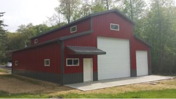
I hadn't planned on posting about the energy systems - they are nothing too exotic. The main power is a 6.2 KW rooftop array, Outback charge controller/inverter and FLA batteries (the new battery technologies are a little too new for my comfort level but any comments are welcome). I am still undecided about the hot water system - I would like to use solar but I might install an interim propane system until I have the time to research things. I really haven't decided yet (but I have piped several 3" conduits between the shop and house to provide lots of flexibility).
Shutters are a good idea and would be fun to design and build. It will be a while before I am finishing the exterior of the house so I have time to give it some thought. I think you described your shutters in a previous post on this forum so I will look that up. Thanks for your comments.
Great Job
Rob,
I've been following this site for a number of years, and rarely see posts from this neck of the woods (I live on Lake Clear, only a short drive away from you). I really like to see your floating slab design as so few houses are built that way around here. My house happens to be one of the rare ones on a slab, although it was built in the 70s. I look forward to the rest of your posts, especially on the roof insulation as I have to rebuild my roof, and maybe I can borrow some ideas!
Simon
Rob, I've visited your timberframe blog many times for inspiration. Very nice work. What dimensions did you make the thickened edges of the concrete?
Log in or create an account to post a comment.
Sign up Log in