

More Building Science


If you want to kill the thermal performance of your insulation, you can take your pick of several excellent ways to do so. Of course, you could just not install insulation. (It happens, even in new construction.) You also could install the insulation unevenly. Or you could interrupt the insulation with more conductive materials, like wood. But if you want to take your insulation-killing skills to the next level, use steel.
The benefits of exterior continuous insulation
My article on series and parallel heat flow in walls shows that you don’t always get the R-value on the label of the insulation you install. For example, let’s say you build a 2×6 wood-framed wall with studs spaced 16 inches on center. Then you put R-19 fiberglass batt insulation in the cavities with no other insulation. Cover it with drywall on the inside and sheathing and cladding on the exterior.
Do you have an R-19 wall? No, when you average the effect of the wood studs and add in the other materials (e.g., drywall, sheathing…), you end up with R-15.8. That’s a 17% reduction from what it says on the label. When you add in the effects of the other framing (e.g., top and bottom plates, corners, rough openings…), the net thermal resistance drops even lower.
One way designers improve the thermal effectiveness of wall insulation is to add continuous insulation to the outside of the wall. If it’s truly continuous, that improves the thermal performance tremendously. Instead of putting R-19 in the stud cavities as above, let’s say you put R-19 continuous insulation on the outside of the wall. That results in an average R-value of 22.9, an improvement of 21% over the labeled insulation R-value and 45% over the R-15.8 we got above.
But how does the attachment system for exterior continuous insulation work? And does it degrade the thermal performance? Let’s look at the three most popular methods.
Vertical z-girts
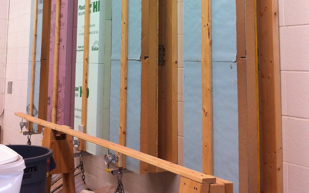
What got me thinking about this topic was a building under construction near the Energy Vanguard office. The lead photo above shows a closeup of part of the wall. You can see the blue extruded polystyrene (XPS) rigid foam insulation. You also can see the vertical metal strips every 16 inches apart. Those are called z-girts.
![Vertical z girt attachment system for exterior insulation before insulation is installed [Photo from RDH Building Science report]](https://www.energyvanguard.com/wp-content/uploads/2023/03/exterior-insulation-vertical-z-girt-attachment-rdh.jpg)
![Diagram of a verical z girt [Chart from RDH Building Science report; link below]](https://www.energyvanguard.com/wp-content/uploads/2023/03/vertical-z-girt-exterior-insulation-attachment-diagram-rdh.png)
Installing the z-girts horizontally gives you a bit of improvement, but it still has a thermal efficiency of only 30-50 percent. Using crossing z-girts, where you do one layer vertical and the other horizontal, is another step in the right direction, with an efficiency of 40-60 percent. Going with fiberglass or other nonmetallic materials for the girts gives you a bigger boost.
Clip-and-rail attachment
A second way to attach exterior insulation is with a clip-and-rail system. This reduces the contact at the wall because the clips don’t run the whole length of the rails. Also, the clips, rails, or both can be made of fiberglass or other nonconductive materials. Or they can be made of less conductive stainless steel.
![Clip-and-rail attachment system for exterior insulation before insulation is installed [Photo from RDH Building Science report; link below]](https://www.energyvanguard.com/wp-content/uploads/2023/03/exterior-insulation-clip-and-rail-attachment-rdh.jpg)
Long screws
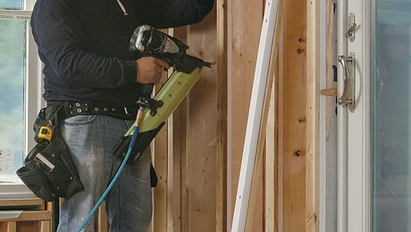
Using long screws is probably the most common way exterior insulation is attached to walls in new home construction. The screws go into wood strapping, girts, or hat channels on the outside, then all the way through the insulation, and then into the structure. The photo below is from the RDH report and shows how that system works with wood strapping and three layers of mineral wool insulation on the exterior.
![Attaching exterior insulation with long screws [Photo from RDH Building Science report; link below]](https://www.energyvanguard.com/wp-content/uploads/2023/03/exterior-insulation-long-screws-attachment-rdh.jpg)
Building science labs are still testing various configurations and attachment systems. The photo below shows a test of long screws through two layers of 2 inch thick rigid foam 8 feet high. Hanging from the bottom of each is a bucket of rocks. A deflection gauge measures how much the weight pulls it down. The answer is that if you do it right, it works.
Now, the screws aren’t free of thermal penalties. They’re made of metal and thus conductive. But there’s a lot less area for heat to conduct through with screws. And then there are two kinds of screws: galvanized steel and stainless steel. It turns out that stainless steel is great for structural use, especially where corrosion can be a problem. And they’re also great at reducing the thermal penalty because they’re not nearly as conductive as galvanized steel. Of course, the penalty with stainless steel is that it’s more expensive.
The thermal performance of various attachment systems
The chart below is from the RDH paper. As you can see, galvanized steel vertical z-girts—like the ones I saw yesterday—are the worst. The two best, at greater than 90 percent thermal efficiency, are stainless steel screws and fiberglass clips with no screws. Everything else falls somewhere in between.
![Thermal effectiveness of different attachment systems for exterior insulation [Chart from RDH Building Science report; link below]](https://www.energyvanguard.com/wp-content/uploads/2023/03/exterior-insulation-attachment-systems-thermal-effectiveness-rdh.png)
Download the RDH paper: Cladding Attachment Solutions for Exterior-Insulated Commercial Walls
Also see papers on thermal bridging from Building Science Corporation, like A Bridge Too Far, by Joseph Lstiburek, PhD, PE.
Allison A. Bailes III, PhD is a speaker, writer, building science consultant, and the founder of Energy Vanguard in Decatur, Georgia. He has a doctorate in physics and is the author of a popular book on building science. He also writes the Energy Vanguard Blog. You can follow him on Twitter at @EnergyVanguard.
Weekly Newsletter
Get building science and energy efficiency advice, plus special offers, in your inbox.


6 Comments
Does anyone have experience with a specific product as an example of the fiberglass clips mentioned? Thanks.
NS Builders has a good video talking through their implementation of fiberglass z-girts (paired with Rockwool) on a project, for both walls and a roof assembly: https://www.youtube.com/watch?v=rmMcP9fTQFQ
I'm not sure what product they used, but the orange color looks like the orange of Armatherm's product https://www.youtube.com/watch?v=GgfmCltp0KY
One thing that you notice when you watch the NS Builders video is that there are some thoughtful details you can incorporate, like possibly running partial (4") clips vertically, reducing thermal bridging potential, while running a full rail at the edges to help reinforce the edges and prevent wind issues, or thinking through what dimension of insulation to run on the roof assembly to handle the load (they had to cut their Rockwool boards thinner to reduce spans between the girts on the roof deck).
Watching the video, you also notice that, when using z-girts, you miss out on the chance to horizontally offset your layers of Rockwool boards. It would be interesting to see a lab test of a comparison between offsetting insulation layers (and running long stainless steel screws through) vs. using the z-girts (and not offsetting the Comfortboard). Another upside to the z-girt, of course, is that your screws are short and are right against your sheathing, so you don't have to worry about missing the studs with the long screws.
I've also seen reference to a product called GreenGirt, but, as with Armatherm's z-girts, I have no experience myself.
Just confirming this. I’m at the New England Building Science Symposium, and Steve Baczek just mentioned the Armatherm product by name as a z-girt for use with Rockwool / continuous insulation.
https://www.cascadiawindows.com/products/cascadia-clip
Those steel z girts were obviously designed by a steel company executive with a lot of stock in fossil fuel companies. Pretty much a 'we are building a steel building with steel studs and using self drilling screws to hold this baby together' type of solution. Pretty sure a bunch of the web could be removed to take the sin off the thermal transfer
That said that amount of diminishment of the r value seems high, or perhaps it is assuming a level of crappy install that is probably pretty accurate
Dear Allison: First, thanks for a great article - highlighting the problems with thermal bridges. We wrapped our homes in Massachusetts with thick foam board, which broke all of the thermal bridges created by all of the wood framing. Another important note: This also significantly improves the ability to air-seal your walls, particularly in a remodeled home. Effective air sealing is almost as important as good insulation.
Second, there is another way to ruin your insulation; if you use polyisocyanurate foam board, know that it absorbs water like a sponge, which kills the R-value and can encourage rot in adjacent wood framing. The faces are protected by poly or foil sheathing, but the edges are very vulnerable to water leaks, particularly from above. If you install polyiso board on the exterior, be sure to carefully seal the edges, e.g. with flashing tape. XPS foam board does not absorb water.
It is also important to note that if you decide to 'wrap' your house with insulation, it must be thick enough to prevent condensation on the sheathing in winter. The required thickness / R-value varies with your location and 'climate zone'. See: https://www.greenbuildingadvisor.com/article/calculating-the-minimum-thickness-of-rigid-foam-sheathing The thickness needed for roofs covered with foam board is higher; see: https://www.finehomebuilding.com/project-guides/insulation/choosing-right-thickness-exterior-foam or IRC Table R806.5.
I hope this is helpful.
Mark
Log in or create an account to post a comment.
Sign up Log in