

More Building Science


Thermal imaging has numerous uses and benefits many different trades. It does everything from surveillance and industrial maintenance to checking someone’s temperature. For this post, I’ll discuss interpreting images in the residential construction field. And because it’s important to have at least a basic understanding of how the camera works and adjustments that can be made to the different camera settings, I’ll start by briefly discuss a few of them.
Camera settings
Newer thermal imaging cameras have similar settings, regardless of the manufacturer. Because I submit the photos I take to a homeowner or other interested party, I want the image to be easily interpreted. I always set the camera to overlay the digital photo on the thermal image. This setting is called MSX in Flir’s cameras and Hikmicro calls it Fusion. This process can be manipulated in software provided by the manufacturers. If not using the software, you’ll want to take the photo with this option selected in the camera’s settings menu.
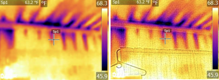
The added details of the photo can help the thermographer and homeowner more easily identify the locations of problem areas in the image. In the example photos above, we know the problem areas are above the curtain, but this isn’t obvious without the digital photo overlay.
I use the iron (flir) or ironbow (Hicmicro) color palette; it shows the purples and blacks as cold areas and yellows and white as warm areas, which in my option, is easiest for a homeowner to understand.
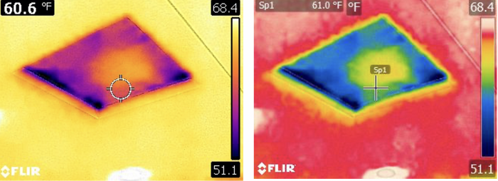
The images above show the iron or ironbow palette compared to the rainbow palette. Whichever is chosen, you want to make sure the customer understands what the different colors mean.
When starting a thermal imaging scan, I show clients the handprint-on-the-wall trick. By placing my hand…
Weekly Newsletter
Get building science and energy efficiency advice, plus special offers, in your inbox.

This article is only available to GBA Prime Members
Sign up for a free trial and get instant access to this article as well as GBA’s complete library of premium articles and construction details.
Start Free TrialAlready a member? Log in


One Comment
Good advice and overview.
Note that uncoated glass has pretty high emissivity, 0.84, a lot closer to typical stuff like painted drywall than to reflective metal which can be 0.1 or lower. So it is possible to get a pretty good reading of glass temperature. However, you can often see an image of the camera operator reflected from a sheet of glass. This shows up with glass more than with typical building surfaces because the smoothly polished surface preserves the image well, not because the reflectivity is very high. To avoid affecting the temperature reading or image, you can simply take the image from an off-axis angle, so so that what is reflected is primarily room temperature surfaces, not a hot-headed human. For best accuracy in the temperature readings, you can set the emissivity in the camera to 0.84, but then the other surface temperatures will be less accurate, and it's rare that a precise measurement of glass temperature is the main objective of the survey.
Log in or become a member to post a comment.
Sign up Log in