

More Guest Blogs


Editor’s note: This is one in a series of blogs detailing the construction of a net-zero-energy house in Point Roberts, Washington, by an owner-builder with relatively little building experience. A list of Matt Bath’s GBA articles can be found at the bottom of this page. You’ll find Matt Bath’s full blog, Saving Sustainably, here. If you want to follow project costs, you can keep an eye on a budget worksheet here.
One of the things I was most excited about, yet also most apprehensive about, was installing the heat pump.
Installation of refrigerant systems like air conditioning units and heat pumps is a delicate process and requires quite a few expensive tools. Refrigerant gas is odorless yet it can be very dangerous to one’s health should it leak. That said, heat pumps are absolutely incredible innovations and it is completely mind boggling to me why more people don’t have one.
The average American has a natural gas furnace with an efficiency of about 85%, meaning that only 85% of the energy you pay for actually heats the house. The rest is lost out the exhaust duct. Then, homeowners typically have an entirely separate machine—an air conditioner—to cool their home. The heat pump replaces both of these units with a single, wonderful machine that is up to 300% efficient! Three times as much energy that’s needed to power the device is returned as heat.
What a heat pump really does
You might recall from your high school physics class that energy cannot be created or destroyed, so how could a heat pump possibly create more heat than the energy that is put into it?
The answer is that a heat pump doesn’t create heat at all! It uses the small amount of energy you power it with to move heat. When you want to cool the house it takes heat from inside your house and moves it outside. When you want to heat, it takes heat from outside your house and moves it indoors.
Now you might be wondering, when I want to be heated, it is usually cold outside. How could a heat pump possibly find heat outside on a cold day to move indoors? The answer to this is that heat is relative. If it’s 20°F outside, that may seem cold to you and me, but that might be a warm day for someone in Antarctica. On a cold day, there may not be as much heat outside as on a warm day, but there has to be some heat or the temperature wouldn’t be able to get any lower. In fact, the temperature at which no heat exists is -459.67°F. Now that’s cold!
So a heat pump moves heat. The Fujitsu I purchased is the most efficient unit you can buy at the moment, and it has the ability to find heat even when it is -15°F outside, which would be virtually impossible in the area where I am building.
The way it performs this function is quite complex, but I will drastically simplify it for you. First, you have to understand the simple law of physics that says temperature and pressure are directly related. If you have ever used a pressurized spray can before you might recall that the can gets colder as you are spraying. This is because the pressure inside the can decreases as the contents are sprayed out. The lower pressure inside the can results in a lower temperature.
So my heat pump has a long copper tube full of refrigerant called R410a. When you want to heat up the house, the refrigerant moves through the tube from inside the house to outside, where a fan blows air across it. Even though it is cold outside, the refrigerant is even colder so it warms up as the fan blows air across the tube. That refrigerant is then run through a compressor, which pressurizes it, so it becomes very hot.
The refrigerant runs through another tube back inside the house where a second fan blows air across it. The refrigerant is now very hot, so the air warms as it blows across the tube, and the refrigerant cools off. The refrigerant then travels to what is called an expansion valve, where the volume of the tube holding the refrigerant increases. This reduces the pressure of the refrigerant, in turn lowering its temperature. At this point the refrigerant has returned back outside to where it started it’s journey and the process repeats itself. The only energy the system needs are to run the compressor, the fans, and the controls. None of the energy is used to create heat, and the energy required to operate the machinery is much less than the energy required to create heat.

To cool the air in the summer, the heat pump uses a valve that allows it to reverse the process, moving heat from inside the house to the outside. It’s that simple! There are several performance ratings for heat pumps. The SEER rating is a measure of how efficient the unit operates in the summer, and the HSPF is a measure of how efficient it operates in the winter. If you can find a unit with better ratings than mine, please let me know! To my knowledge it is the most efficient unit you can buy.
Indoor and outdoor components
A heat pump consists of an indoor unit and an outdoor unit that are connected by a bundle of flexible piping and wiring called a lineset. The lineset provides a path for refrigerant, condensation, electrical power, and electrical communication signals to go back and forth between the two units.
The indoor unit is installed first. A metal bracket is provided for mounting the unit on the wall and a template also is provided to ensure that the hole in the wall for the lineset is cut at the proper location. All that you need to do is mount the bracket to the wall with the screws provided and use the template to drill the proper size hole in the wall. You then hoist the indoor unit into place, threading the attached piping through the hole as you hang the unit on the mount.
The next step is to attach the lineset. I purchased a lineset that came with an electrical cable already bundled in but you can purchase that separately as well. I also purchased a drain hose for the condensate the unit produces. Cold air can’t hold as much moisture as warm air, so any time you are cooling warm air you will create condensate. If you don’t want this moisture to drip out of the unit as it builds up, you must provide a path for it to go outside or to a drain. The drain hose was easiest to install; it just screwed to the connector attached to the indoor unit.
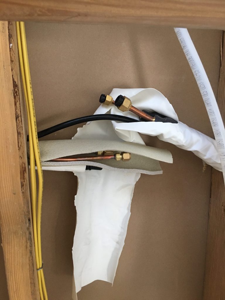
Next, I connected the electrical wiring to the indoor unit. The wiring contains four wires, two for power (+,-), one for communication, and one for ground. You simply strip the wires and attach them under the screws, keeping in mind which color goes with which connection. The last two connections for the lineset are for the refrigerant. There is a larger flexible pipe called the suction line that carries condensed refrigerant and a smaller one, called the vapor line, that carries vaporized refrigerant. These pipes are under very high pressures so the connectors, called flare fittings, must be tightened with a torque wrench to just the right amount of tightness. I purchased a special Crescent-style torque wrench because the regular socket style won’t work for this application. The correct torque to use for each pipe was listed in the installation manual.
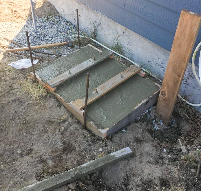
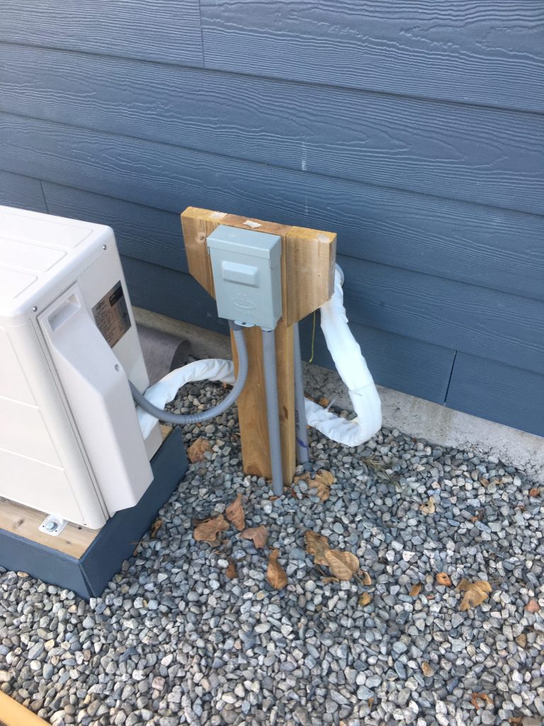
The final and most complex step is to install the outdoor unit. First, I poured a small concrete pad to ensure the unit would remain stable and level. I embedded anchor bolts in the concrete before it cured and after it was completely cured, I bolted some pressure-treated wood to them. I built a stand with more pressure-treated wood and then bolted the unit to this. The stand will ensure that winter snowfall will not damage the unit. I finished the stand with some scrap siding to give it a nice, clean look. Next, I used a post hole digger to mount a pressure treated 2×6 into the ground next to the unit and attached an AC disconnect to it.
I had already run the wiring for the heat pump from the main panel to a junction box inside the wall under the heat pump. At this junction box, I had transitioned the wiring from indoor type wiring (NM) to outdoor rated wiring (UF) and then run the UF cable in a conduit to the outside.
I had installed the conduit way back before pouring the foundation of the house. This kind of advanced planning was important because it allowed me to have fewer holes in the walls of the house and fewer pipes and wires taking up valuable space for insulation in the exterior walls of the house than the average heat pump installation does.
All I had to do now was dig down to locate the conduit and pull the UF wire out and run it up the side of the 2×6 post and into the AC disconnect. Then, I ran a flexible conduit from the AC disconnect to the heat pump, and attached the wires to the appropriate screws on the outdoor unit. The unit uses 240 volts, so there are actually two hot wires each carrying 120 volts, instead of the usual hot and neutral wires. There was also a ground wire included.
Connecting the outdoor unit
The next step was to connect the lineset to the outdoor unit. First, I ran the condensate hose to an exterior drain near the outdoor unit. I made sure the hose was continuously sloped downward so water would not pool in a low spot before it got to the drain. Next, I connected the wiring from the lineset to the outdoor unit, ensuring the same colored wires were attached to the same numbered screws as on the indoor unit. Last, I again used my torque wrench to attach the refrigerant piping to the outdoor unit.
It was now time to “pull vacuum” on the refrigerant piping. The refrigerant has a lower freezing point than water, and operates at extremely low temperatures, so the slightest bit of moisture in the piping will form ice crystals and decrease the performance of the system. By pulling a vacuum, I will decrease the pressure inside the piping. This will remove any moisture and/or contaminants in the system.
I purchased a vacuum pump and hoses and connected them to the charging port on the outdoor unit. Next, I turned on the pump and watched as the pressure gauge slowly worked its way towards 29.92 inches of mercury, known as a perfect vacuum. I left the pump on for an hour to ensure that it got as close to that as possible, and then turned it off. I let it sit for 24 hours to make sure there were no leaks in the system, and to be safe, I used a refrigerant leak detector as well.
When I felt good about the integrity of the system, I removed the caps on the refrigerant ports and used an Allen wrench to release the refrigerant into the system. Once the piping was filled with refrigerant, I removed the pump hoses from the charging port and replaced all the caps I had removed.
All that was left now was to turn on the system and test out both heating and cooling operations to see that the system was working properly. The unit comes with a remote control and it is very easy to toggle between heating and cooling modes. It was a perfect day to test both, about 65°F, and the system performed as advertised. There was a little room left in the conduit to run a CAT6 wire for internet and then I used spray foam to fill in any air gaps inside the conduit and to provide some insulation.
Previous posts by Matt Bath:
Designing and Installing a Septic System
Installing the Ventilation System
Weekly Newsletter
Get building science and energy efficiency advice, plus special offers, in your inbox.


10 Comments
“So my heat pump has a long copper tube full of refrigerant called R410a. When you want to heat up the house, the refrigerant moves through the tube from inside the house to outside, where a fan blows air across it. Even though it is cold outside, the refrigerant is even colder so it warms up as the fan blows air across the tube. That refrigerant is then run through a compressor, which pressurizes it, so it becomes very hot. The refrigerant runs through another tube back inside the house where a second fan blows air across it. The refrigerant is now very hot, so the air warms as it blows across the tube, and the refrigerant cools off. The refrigerant then travels to what is called an expansion valve, where the volume of the tube holding the refrigerant increases. This reduces the pressure of the refrigerant, in turn lowering its temperature.”
This is a good attempt at a short explanation of the refrigeration cycle but in the heating mode the expansion valve that is operating is in the outdoor unit just before the coil. The indoor expansion valve is used in the cooling mode.
“Refrigerant gas is odorless yet it can be very dangerous to one’s health should it leak.”
Please tell us about the risks short of burning it and breathing the fumes or releasing hundreds of pounds in a confined space. What other risks are there?
Walta
Risks with refrigerant are that it displaces oxygen, and is heavier than air, not actually toxic by itself. Not really an issue unless you're dealing with hundreds of tons of refrigerant in a pit or confined space.
Heating refrigerant (open flame type temps, maybe 900f+?) it breaks down into phosgene gas, which is toxic. The Navy always told us it smelled like almonds (fire+refrigerant on a submarine would be bad). Google says it smells like fresh cut grass.
The simplified explanation of how heat pumps work is also missing the all-important phase changes from gas=>liquid=>gas that is going on in the refrigerant cycle. The process as-described is closer to what goes on with CO2 refrigerant systems, where the refrigerant remains a gas in all parts of the cycle.
BTW: The Fujitsu -9RLS3's is NOT a "....wonderful machine that is up to 300% efficient...".
It's tested & labeled HSPF 14.2 efficiency indicates (14.2 BTU/watt-hr for the heat pump /3.412 BTU per watt hour for resistance electricity = ) 416% efficiency, which it should be easily achieve or exceed as a seasonal average in a location as temperate as Point Roberts.
Phase change dramatically increases the heat capacity of the fluid and efficiency, but I'm not sure phase change is "all-important" in describing the refrigerant cycle as the cycle works without any phase changes.
Matt you are an inspiration. As someone who is seriously contemplating a DIY of a Fujitsu (or other system without factory-charged lines) I’m following you up until this bit:
>> When I felt good about the integrity of the system, I removed the caps on the refrigerant ports and used an Allen wrench to release the refrigerant into the system...
I always assumed I needed to have a tank of refrigerant at that point to fill the lines. You don’t mention one though... Is there a sufficient mass of refrigerant sitting in the outdoor unit just waiting to fill the depressurized lines? That would certainly make this simpler!
>" Is there a sufficient mass of refrigerant sitting in the outdoor unit just waiting to fill the depressurized lines? That would certainly make this simpler!"
There is a fixed amount of refrigerant pre-charge, and the amount of refrigerant that needs to be added or removed to have the correct amount in the system depends on the size of the refrigerant lines, and the refrigerant needs to be accurately weighed.
The DIY kits from other vendors come with a set of pre-purged/dried refrigerant lines to ensure that the refrigerant charge is at least close to the correct/optimal amount.
The way I understand it, most minisplits come pre-charged with enough refrigerant to cover most installation scenarios (this will be covered in the manual). If you need a longer line set than the maximum recommended in the manual for the pre-charge, a specific amount of refrigerant per extra foot of line is specified, at which point you need a tank, a scale, and probably someone who's familiar with using them.
If the line length of your install is within the recommended length for the pre-charge, installing a minisplit is a DIY job as long as you're comfortable with the steps involved with mounting it, and using a vacuum pump (and sometimes line flaring tools). Of course, if you screw it up you'll be calling an HVAC guy to purge it and start over, and the warranty may be void unless installed by a professional.
>> “and the amount of refrigerant that needs to be added or removed to have the correct amount in the system depends on the size of the refrigerant lines, and the refrigerant needs to be accurately weighed.”
TY Dana!
Not sure if Matt ever chimes in here but I’d be curious to know how he approached this, and whether he had help from a pro.
The amount of refrigerant in the system is enough for common line lengths and there would never, as far as I can tell, be a reason to remove any. If you get over 25 feet or so[install manual would say] you have to start adding refrigerant
I have installed 6 myself although only did the refrigerant on the last one, never changed refrigerant level.
Condensate drain is the trickiest part. Mini splits have a very, very shallow drain pan that with even minor slowing of the drain will cause it to back up and spit out the front
I have a unit that has a 14 foot drop and a pretty good initial slope to the drain and if I don't have the bottom outlet just right, it will back up. If you have a standard outside wall install where it immediately pops out the wall and straight down, this is not a big issue. All of my current units are in inside walls so particular care must be taken
"If you can find a unit with better ratings than mine, please let me know!" I think the ratings of the Carrier 38MPRA are better, but I would buy what you did instead.
I'm curious to know where you bought your equipment? And why can't you attach the AC disconnect to the house?
Log in or create an account to post a comment.
Sign up Log in