
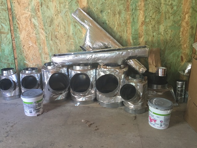
Image Credit: Energy Vanguard
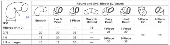
Image Credit: Energy Vanguard This table shows the equivalent lengths for round and oval rigid elbows.
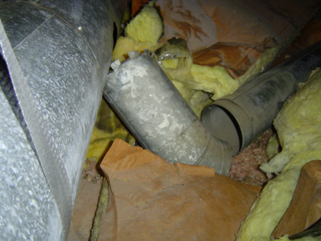
Image Credit: ACCA Manual D This branch duct in a very leaky rigid duct system fell apart when I removed the insulation.
Image Credit: Energy Vanguard
More Building Science


At the end of this month, I’m giving a little presentation at the ASHRAE conference in Las Vegas. Actually, I’m doing one third of the whole presentation, which is titled Flex Ducts, Hard Ducts and No Ducts: Migration Patterns for Duct Hunters (or not) in the Land of Thermal Comfort. My part is on hard ducts.
Chris VanRite is doing flex duct, and Robert Bean will cover the no-ducts part (which doesn’t refer to ductless minisplits but rather to hydronic distribution). We get 15 minutes each, so I’ll elaborate on my part a bit here.
Before duct design
Designing a duct system is important, but there are a few critical steps that come first. Number one is the load calculation using a protocol like ACCA’s Manual J or the ASHRAE Handbook of Fundamentals. You’ve got to know how much heating and cooling you need for each room. Then those BTU/h requirements immediately translate to room-by-room air flow requirements in cubic feet per minute (cfm). It’s done automatically in the software we use (RightSuite Universal by WrightSoft).
Once you know the BTU/h and cfm numbers for the building, you need to select the right equipment. ACCA’s Manual S protocol helps you do that. There’s more to it than just finding a piece of equipment that meets the total heating and cooling loads for the home. You’ve got to make sure you adjust for the indoor and outdoor design conditions of the home. Ideally, you have the manufacturer’s performance data tables to help you get it right.
Then you’re ready to start designing the duct system.
Getting the right air flow
If you take a fan out into your yard on a calm day and turn it on, you’ll get its maximum air flow. If you take that same fan and blow the air into a cardboard tube, it has to work against the pressure that builds up in that space. The more you reduce the size of that tube or make it longer or turn the air with it, the more static pressure builds up. And the more the air flow is reduced.
That’s the basic principle you have to work with in duct design. I’ve written previously about the two factors involved in reducing air flow in ducts. One is friction. As the air moves through a duct, it interacts with the surfaces. The smoother that inner surface is, the more air flow you get. The rougher the surface, the less air flow.
The second factor is turbulence. This generally arises when you move air through fittings or when you turn the air. With rigid duct, you turn the air with fittings, but unfortunately that’s not always the case with flex duct.
When air comes out of the air handler, several things happen to it. It gets sent to the various rooms in the house. As it travels through a trunk-and-branch duct system, the quantity keeps diminishing because some of it gets diverted down each branch on the way to the end.
Each section of duct, each fitting, each turn of the air, adds resistance to that air flow because of friction and turbulence. Grilles and registers, filters, and balancing dampers also add resistance. That resistance results in decreases in the static pressure, or pressure drops.
The duct design process
In designing a duct system, you’ve got to know how much static pressure you have to work with and how much you lose because of the factors I listed above. Air handlers are rated for a certain total external static pressure. A lot of times that number is 0.5 inches of water column (iwc). Then you subtract from that the pressure drops of the components that aren’t ducts or fittings. That gives you the available static pressure. That’s how much you have left to “spend” on your duct system. If you overspend with a restrictive duct system, the static pressure goes up and the air flow goes down. Don’t do that.
Friction and turbulence both result in static pressure drops and reduce air flow. The way we quantify this in the duct design process is with total equivalent length. For straight sections of duct, we just use the measured length. For fittings, though, we need to find the equivalent length (explained below) for each one. (They’re in ACCA’s Manual D and the ASHRAE Handbooks.) Once we have those numbers, we add up all the lengths and equivalent lengths of the longest run to find the total equivalent length.
The next step is to divide the available static pressure by the total equivalent length. That results in what’s called the friction rate, which we need to determine the size of the duct. You can use a duct calculator or software to go from friction rate to duct size.
So what exactly is the equivalent length? It’s how long of a straight section of duct you’d need to get the same pressure drop as the fitting. The table of rigid elbows in Image #2 below (from ACCA Manual D) shows equivalent lengths for various shapes and designs of these fittings. Looking through the table, you can see that there’s quite a range. You could use an elbow with and equivalent length as low as 10 feet or as high as 75 feet.
In the duct design process, you’ve got to account for the standard pressure drops in the filter, registers, and grilles. Then you add up the equivalent length of the longest runs in your supply and return ducts. The goal is not to use more pressure than you have available. Pretty simple, right? Not always.
We do third-party HVAC design and we try to be a little conservative with the fittings we choose. For example, we might do our design with a 3-piece elbow that has an equivalent length of 35 feet. If the installer uses a more common 4-piece elbow, the equivalent length is less, so it should result in better air flow than we designed for. Then if they spend that little air flow dividend somewhere else, we’re covered.
When designing a duct system, you have to account for all these things. With rigid duct, you can get more predictable results if you use the fittings called for in the design. With flex, it can be significantly worse than you expect because of what installers do to that stuff. Not that it can’t be done right. I’m fine with flex duct myself, as long it’s used only for straight runs and pulled tight.
Two ways that hard pipe can be worse than flex duct
Hard pipe has less friction than flex duct. You can’t (easily) squeeze it between a drain line and a floor joist. And contractors who use it actually install fittings to turn the air. But in two respects, flex duct has the advantage:
- Hard pipe doesn’t come pre-insulated
- Hard pipe can be leakier than flex — much leakier.
Those flaws are far from fatal, but they do require careful attention during installation. I’ve tested older rigid duct systems that had really high leakage. The one shown in Image #3 (below) seemed to be held together mainly by the rather thin insulation. When I took the insulation off, this branch duct just fell apart.
A few takeaways for good duct design
Let me wrap this up with a few guidelines for good duct design.
- Go for predictability. A straight run of hard pipe is more predictable than a straight run of flex. A straight run of flex pulled tight is more predictable than the typical flex installation. Turning air with fittings is more predictable than turning air with flex.
- Know your limits. The blower you choose limits the static pressure you have to work with. The components you add and the duct system you design must work with that limit. If you overspend on a restrictive duct system, you won’t get the amount of air flow you need.
- A good duct system needs more space than you might imagine. Especially near the air handler, ducts generally need to be bigger and have longer runs than they’re usually designed for.
- Place the air handler in the center of the house if possible. Running trunk lines away from the air handler in two directions makes it easier to get good air flow because of fewer downstream branches than a single trunkline.
- Design to minimize equivalent length but build in some cushion. Make sure your design will work even if the installers make a few substitutions or mistakes.
There’s a whole lot more to this subject than I’ve discussed here. And that’s why there’s a whole book on this topic. It’s called Manual D.
Allison Bailes of Decatur, Georgia, is a speaker, writer, building science consultant, and the author of the Energy Vanguard Blog. You can follow him on Twitter at @EnergyVanguard.
Weekly Newsletter
Get building science and energy efficiency advice, plus special offers, in your inbox.


0 Comments
Log in or create an account to post a comment.
Sign up Log in