

Image Credit: All images: Elden Lindamood
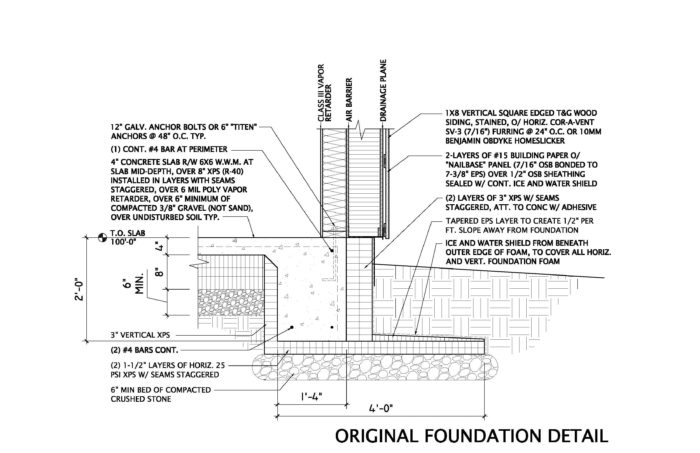
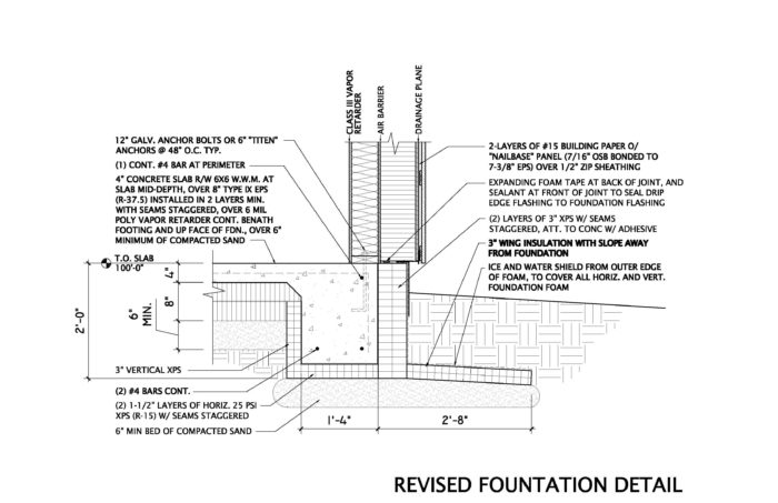
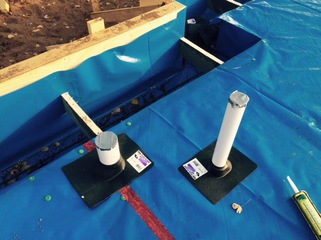
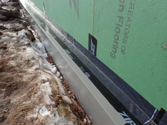
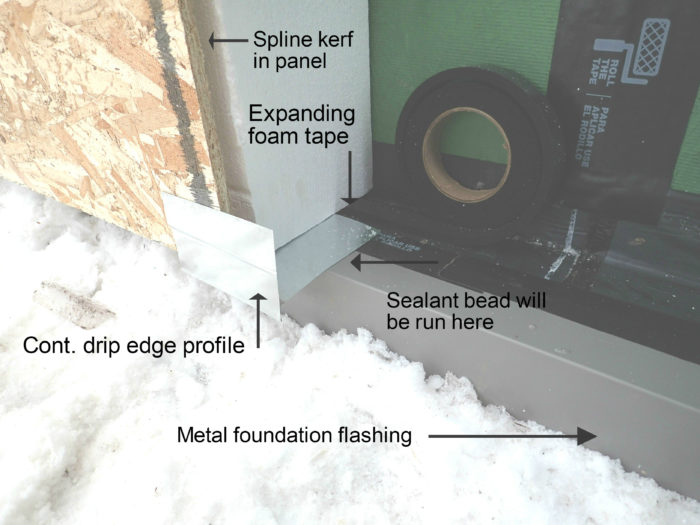
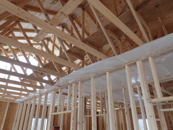
Image Credit: All images: Elden Lindamood The original foundation as I designed it. The next image (Image #3) shows our revised foundation detail. This is the revised foundation detail that I worked out with my builder to improve constructability and reduce cost while maintaining my performance and aesthetic goals. The blue sheeting is the vapor barrier and soil gas barrier. It is installed over the first 4-inch layer of EPS foam and is continuous down and under the thickened slab edge. The builder used rubber flashing boots to create a good seal at plumbing penetrations. The peel-and-stick flashing that extends up the wall sheathing is continuous over the top of the foundation foam and is lapped over the peel-and-stick membrane that protects the foam from insects and rodents. The gray metal flashing is primarily a finish material which is taped in place and held against the wall by the backfill. The galvanized metal continuous drip edge will be stapled to the face of the nailbase OSB. That will then be set in a liberal bed of sealant to connect the drip edge flashing to the foundation flashing. An expandable foam tape will be placed at the back of the joint to help fill the gap created by the heaved gray metal flashing. Note that the gap between the OSB and the EPS is machined into the EPS so that the panels can accept a spline at the joints. The mitered nailbase panel at an outside corner. The gap will be filled with canned spray foam. I had the truss manufacturer add a horizontal member to each truss to create a catwalk above the insulation level. Now if I ever have to do work in the attic, I won’t have to wade through 24 inches of cellulose. The poly air barrier at the ceiling was installed before the interior partitions were framed so that it the air barrier is continuous over the interior walls. Note that the poly is turned down and sealed to the lower top plate rather than upper one as is typically done. This illustration shows how air leakage can bypass a double top plate in what I consider typical construction, compared to how we addressed the top plate using the lower plate as a continuation of the air barrier from the interior ceiling air barrier plane to the exterior air barrier (at the Zip sheathing).
More Guest Blogs


This is the second part of a blog series by architect Elden Lindamood about the design and construction of his own home. The first installment was called A Low-Energy House for Northern Minnesota.
Progress has continued on the new house, and a few things have come up along the way to warrant minor changes in the foundation insulation details and window installation. It is refreshing to work with a builder who asks questions and works with me to alter things and arrive at alternate solutions that seem more practical and buildable to him without losing my performance or aesthetic intent. Too many times I have arrived on project sites to find a builder who simply “did it the way he’s always done it” despite the bid set that specified otherwise.
I’d like to share some of the details that my builder and I altered from the original design. I’ll also share a few experiences with the nailbase insulation panels in case a reader is considering that wall construction method.
Should the base be crushed stone or sand?
One of the first conversations I had with my builder, Steve Johnson, that resulted in an alternate detail involved the insulation surrounding the frost protected shallow foundation (see Images #2 and #3, below). The original and revised details seem very similar at first blush, but there are a number of differences which were all carefully considered for constructability and performance.
Right out of the gate, the excavator encouraged me to use sand for the base rather than the crushed gravel that I had specified. My original intent was to take advantage of crushed stone’s lesser tendency for capillary action on a site with a high water table to help ensure that the slab, the slab insulation, and horizontal wing insulation would stay dry. In talking it through with the builder and excavator, however, I agreed since my site is dead flat for hundreds of feet in any direction, and since there was no way to run a drain tile to daylight, that using sand (which would be cheaper and easier to work) was an acceptable solution in this instance.
Had it been a full basement below the water table, I wouldn’t have relented. Steve also suggested that he could run the sub-slab vapor barrier / soil gas barrier continuously down, under, and up the form for the thickened slab edge, helping to protect it from capillary moisture (see Image #4, below). I agreed that was a good plan, and we were on our way.
Foundation insulation changes
As the drawings show, I switched from XPS to Type IX EPS for the under-slab insulation. This was primarily a matter of cost and availability, with a very small energy penalty (and a slight global warming potential improvement). The builder installed the EPS in two 4-inch layers, with the vapor barrier placed between the two layers.
We then discussed my detail showing a single continuous sheet of insulation from beneath the footing, extending out to form the horizontal wing insulation. I thought I was being helpful by detailing it so Steve wouldn’t have to cut any more foam than necessary, but because of how he wanted to set his wood foundation forms, that was going to be difficult. I was hesitant to let that one go because I was concerned about a joint or gap at the lower, outer slab edge. However, Steve wanted to install the vertical exterior foam post-pour, so the vertical insulation could then go on prior to the wing insulation, creating a lapped joint that I was happy with.
This detail also allowed Steve to slope the exterior wing insulation away from the house without the need for the extra tapered insulation that I envisioned placing on top of it. Additionally, Steve asked if the 2’0″ dimension that I had initially indicated from the top of slab to bottom of thickened edge was code-required. I looked into it and determined that the 2’0″ dimension was required to the bottom of foam, not the bottom of the concrete. This allowed Steve to cut his forms and vertical insulation to 24 inches instead of 27 inches.
All of this discussion lead to a good foundation detail that fit the builder’s preferred process, met my performance goals, and saved some time and money. This is how I wish all projects would go — but I digress.
Insect worries
One of the things about a frost-protected shallow foundation that has always made me uneasy is the potential for insect intrusion into the foam. Northern Minnesota is not a termite zone, but will it be 100 years from now?
I searched fruitlessly for information on how deep in the soil termites and carpenter ants will burrow. Regardless, I wanted to protect my foam, and also block any possible path from the foundation insulation into the wall insulation.
I initially explored wrapping all of the wing insulation and the vertical face of the foundation foam with stainless-steel screen cloth, but that was prohibitively expensive, especially for something I wasn’t sure was necessary. I eventually settled on covering the top of the wing insulation with Ice& Water Shield, and extending that up the face of the foundation. That would later be lapped with more peel-and-stick flashing to connect the Zip sheathing to the face of the foundation.
This created a nice barrier against burrowing insects (and varmints) from the exterior, and broke the potential path between the foundation insulation and the exterior wall foam with a peel-and-stick flashing. I also couldn’t find any information about whether ants or termites would chew through Ice & Water Shield, but I assumed they would not. Subsequent layers of metal flashing would further reduce that risk.
Frost heaving pushes up the flashing
Steve placed a prefinished metal flashing over the top of the peel-and-stick flashing to protect and finish the foundation (see Image #5, below). This was then taped, and we were ready for the nailbase panels — with one small hitch.
Since we are building in the winter, in northern Minnesota, despite the fact that the weather has been mercifully mild so far, winter construction brought its first complication. We had a significant amount of rain before I backfilled the trench against the metal foundation flashing. The soil that I backfilled with was sandy in many places, and muddy topsoil in others. The soil was saturated.
A few weeks after that was done and Steve was getting ready to place the first nailbase panel, he noted that the wet soil had grabbed the metal flashing as it froze, and heaved it up about 1/4 inch. This meant that the joint between the bottom of the nailbase panel and the top of the foundation insulation wouldn’t be as tight as I hoped.
Since there wasn’t much that could be done, shy of waiting until next May, we decided to place a strip of expanding foam tape at the rear of the joint, and a liberal bead of sealant at the front of the joint (see Image #6). This should serve to keep insects and vermin out of the joint.
I’ll definitely watch the joint over the next couple of years as things settle in to be sure it doesn’t open up. If it does, I’ll have to caulk it. Steve is inclined to think it will never be a problem.
Sealing the nail heads
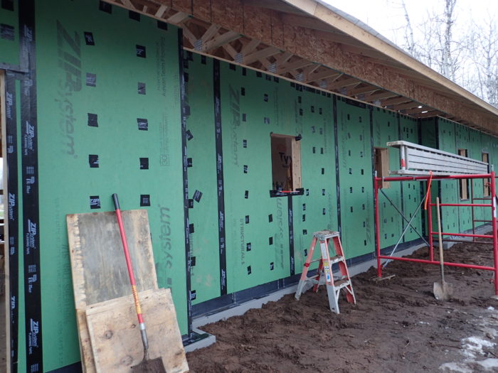
With the foundation complete, the above-grade walls were framed and sheathed with Zip System OSB. The joints were taped — the taped sheathing will be my air barrier — and the sheathing was also taped back into the framed window openings. Since this is for air control only, and the windows will be “outies” at the face of the nailbase panels, the openings didn’t need to be flashed at the Zip sheathing, but simply sealed.
Even though Huber says you don’t need to tape or seal the nail holes in the panel fields, my partner Catherine and I spent a few hours taping little squares of Zip tape over each nail hole. It may not make any difference, but since I am going for a ridiculously tight envelope, I thought it was worth the minimal effort (see Image #1 at the top of the page).
The nailbase panels cupped
A previous project taught us a few things about using nailbase panels for our high-R walls.
The first issue is that the nailbase panels were cupped. Having an OSB skin on only one side makes them less stable than a SIP, so they all seem to cup with the center of the OSB skin moving outward about 1/4 inch to 1/2 inch.
This isn’t problematic in and of itself, but it does make it critical that the attachment screws get a good purchase in order to pull the center of the panel tight to the wall. The panel manufacturer, Extreme Panel, usually provides 8 1/2 inch self-tapping screws with their 8-inch nailbase panels. These screws are long enough (normally) to grab the structural sheathing beyond.
Note that the manufacturer only requires you to screw into the sheathing, which is why the 8 1/2 inch screws are what they usually provide. Because of the cupping issue, we ordered 9 1/2 inch wood-tipped screws instead, hoping to get a better bite in the sheathing and pull the panels tight. (I should mention that the nailbase manufacturer was very helpful in ordering the non-standard screws, and has been a pleasure to work with).
Even with these more aggressive screws, Steve said he thinks it is best to hit a stud so that he doesn’t just strip out the hole trying to pull the panel center tight. He added that if he were to do it again, a 10-inch screw might be preferred.
The nailbase skin is smaller than the nailbase insulation
We also stipulated that the nailbase panels have an OSB skin measuring 47 3/4 inches x 95 3/4 inches and an EPS panel measuring 48 inches x 96 inches. This was done on the recommendation of a builder; based on experience on a previous job, he thought it would aid in getting the joints between panels really tight.
It turns out that although the manufacturer was very accommodating at providing the panels we requested, the OSB skins aren’t all glued perfectly centered, or straight, on the foam panels. Thus Steve learned that to ensure accuracy, he needed to measure his cuts off the foam, not from the OSB edge.
Since this is winter construction, the panel adhesive, which you are to apply liberally between each panel, is cold and a bit stiff. That means that the panel joints don’t seem as tight to me as they might be if the sealant was more easily squished. Again, there isn’t much we can do about that except wait until May, so we’ll make do.
Fortunately, because of panel screw alignment with the studs, the panel joints don’t often fall on a stud in the cavity wall and the potential for thermal bridging at a panel joint is somewhat minimized. It does make me reconsider the merits of multiple layers of foam with staggered seams, though.
Steve also commented that he really liked the large washers provided with the screws, and that it was much easier to install the panels in a flat plane than it is to install furring strips directly over thick foam.
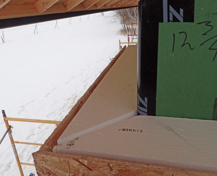
The nailbase corners come together in a mitered joint
Steve opted to miter the outside corners of the nailbase panels. He cut them short so that he could fill the gap with canned spray foam.
The manufacturer suggested a butt joint with a piece of extra OSB glued on, but Steve liked the miter joint idea better. He did the second corner with a 43-degree cut so the gap gets wider toward the outer edge, allowing for easier filling with the canned foam (see image #7, below). He is using a track saw with a chainsaw-type attachment that allows him to make his miters in the thick material.
Other than making the exact kind of mess you’d expect from cutting EPS with a chainsaw, the cuts are straight and the cutting method seems to work great. His non-mitered cuts are executed with a Festool track saw, cutting 3 inches deep on each side and then finishing off the unreachable center of the cut with a handsaw. Using multiple layers of thinner foam would make cutting easier because you could use a table saw or circular saw, but I think the time lost with the nailbase panels is made up in the speed of installation. I’ll ask Steve to share further impressions on the process when the job is finished.
Also note that I opted to extend the trusses out over the nailbase panels, as opposed to running the nailbase panels up to the roof deck (see Image #1 at the top of the page). I did this because at the time it seemed easier than notching the nailbase panels around the truss tails or holding them below the soffits. Also, the nailbase panels are expensive, so reducing the area covered by the panels and filling the area with the attic cellulose seemed more prudent. You really could do it either way, but this is the direction I chose.
Planning for an attic catwalk
I had the truss manufacturer add an additional single horizontal member to each attic truss at 28 inches above the bottom of the trusses. This allowed Steve to install a catwalk using plywood salvaged from the concrete forms. The catwalk runs the length of the attic (see Image #8, below). This added a couple of hundred dollars to the cost of the truss package, but if I ever have to do any work in the attic, I think I will be happy I don’t have to wade through 24 inches of cellulose.
Steve suggested some good installation details for the ceiling air barrier. He installed the polyethylene before the interior partitions were framed, so the membrane is continuous across the top plates of the partitions. He instructed the plumbing and electrical trades that he wants as few holes as possible in that membrane.
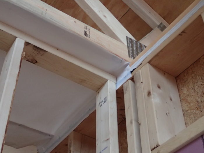
He also sealed the ceiling air barrier to the lower of the two top plates at the exterior walls (see Image #9). This makes the air barrier continuous through that plate to the exterior Zip sheathing. (The Zip sheathing was also sealed to that plate when the sheathing was installed.)
When penetrations are made in that plate, the penetrations can be sealed more easily from the interior side of the penetration, eliminating the possibility of air infiltration between the plates, which I have seen when conduction blower door tests at other jobs (see Image #10).
In my next blog, I hope to share some photos of the window installation and to talk about the changes we made to those details. In the meantime, Steve is trying to get the envelope closed in just as the Minnesota winter is getting really harsh.
Elden Lindamood is an architect with Wagner Zaun Architecture in Duluth, Minnesota.
Weekly Newsletter
Get building science and energy efficiency advice, plus special offers, in your inbox.


16 Comments
Specification Projections
Elden,
Looks like it should be a nice place.
I haven't read every word of your articles, and may have missed some things, but can you answer:
--what is your simulated/projected mechanical heating load for the winter season, and what system will you have to help meet that load?
--what heating capacity do you expect to need at design temperature?
--what solar fraction for the seasonal heat load from passive solar glazing do you expect to get? Does your energy simulation software give you that projection, and does it show net solar gain from the glazing by month.
--
Specification Projections - Reply
Rick,
The projected mechanical loads were modeled using REMRate software. They are:
Heating Design Load: 12.7kBtu/hr
Cooling Design Load: 7.3 kBtu/hr
Heating Annual Load: 17.2 MMBtu/yr
Cooling Annual Load: 5.7 MMBtu/yr
Heating/cooling is by an 12KBtu fujitsu ducted mini-split (12kBtu cooling, 16kBtu heating), backed up with 3500 watts of electric radiant cove (each unit individually thermostatically controlled), and a wood burining stove.
I am working on the solar gain contribution computation. A quick exercise I did with REM was to change the south windows to fully shaded year round and look at the difference. In doing that, the Heating Design Load stayed the same (as it should), and the Cooling Design Load decreased by 1.4 kBtu/hr (I knew I was getting a bit of unwanted gain for part of the year). The Annual Heating Load increased 2.7 MMBtu/yr, and the Annual Cooling Load decreased by 2.4 MMBtu/yr, indicating only a modest net gain of 300,000 Btu for the year (which is like 4 gallons of propane or something).
That being said, REM isn't as nuanced as PHPP, and we are planning to look at it in PHPP to verify the REM numbers and get a better month-by-month picture. Also, REM doesn't (can't) account for occupant behavior like opening windows, so it is maybe a fool's exercise. I'll be monitoring it over the next few years to see.
Woodstove in a tight house
Elden - How are you accommodating the wood stove? Will there be direct combustion with outside air? Masonry chimney or stainless steel? Thanks for sharing your efforts.
Elden
A design that includes somewhere to store wood for the wood stove. What madness is this?
Woodstove in a tight house - response
Kevin,
The woodstove will have a stainless steel chimney. It will not have outside air piped directly to the unit. It will take some awareness on my and Catherine's part as to how it is functioning, but we discussed it and are willing to make that commitment.
I will be installing an Electro Industries MUA unit that has a fan and a 1kw heating element with a thermostatic sensor (you can set the incomming air temp at which you want the element to come on). That will be controlled with a wall switch by the range. I opted for the wall switch control rather than a current sensor on the range hood specifically so I can turn on the MUA unit if the wood stove needs it, without turning on the range hood which would be counter productive. I expect to maybe use the MUA unit to pressurize the house during stove start-up, but my hope is that it will be fine once the stove is hot without the MUA unit on.
We also discussed that we may have to crack a window if the woodstove is lit and we want the range hood on high. I don't expect that to happen that often. It is a bit of an experiment, and I might have to try plan-B later, but only time will tell. We just tested the house yesterday and got 0.23 ACH50, pre-sheetrock but also without the range hood and MUA vents installed, and we identified the attic hatch as a "big" leak, so it is going to be a very tight house. Of course I'll share my epxeriences with the stove in due time.
I have a fairly tight workshop heated by a wood stove too. When I close the door quickly, I know I get a puff of backdraft smoke out of it. We'll see if the same thing happens in the house.
Response to Malcolm
Thanks for noticing Malcolm. That cracked me up.
Thinking more about the solar contribution
In my comment above I modeled the solar contribution of the southern glazing and offset that with the additional cooling load "penalty" for that glazing, all measured in Btu's. In pondering that on my drives back and forth to the office I decided that was maybe a slightly slanted way to look at it. If the house was heated with propane, then I wouldn't have a propane air conditioner, so I shouldn't really offset that with the unwanted gain...or should I?
The model indicates that the heating load offset by the south windows is 2.7 MMBtu/yr. If my primary fuel source was propane (which it isn't), that would reduce my annual consumption by about 30 gallons of propane per year (2.7MMBtu divided by (91,000 btu/gallon of propane X 0.95 adjustment for boiler effeciency). The total annual consumption for the year with propane would be 199 gallons using the same formula. Thus, in that light, the solar gain offsets the heating load by about 15%. That sounds a bit more significant.
Any thoughts on what the relevant information is in regard to the solar gain? Or thoughts on what the solar contribution should be if it were "ideal"?
Solar Fraction
Elden,
Thanks for the specs so far. I like to see all the specs of a house, but many GBA articles are not giving them in recent years. They used to show them more and I wish they would go back to it.
It would be nice if you could get software to calculate your solar fraction (contribution) specification, and post it.
Wing insulation moisture loading
Nice project and blog Elden. I wanted to share the results of an unintended test of 25 year old XPS buried in sand. Built in 1990, my home's frost protected shallow foundation has one 3" layer of XPS wing insulation consisting of sloped 48" wide sheets around the perimeter approximately 12" below grade. Last summer we excavated an area along 16 feet of wall to prep for a new stone patio. The foam had to come out to get deep enough for the planned layer of compacted crushed sandstone base with a sandwiched layer of new XPS foam insulation under the whole patio. The original foam in that area consisted of two brands, blue and yellow. All of the old foam we removed was saturated with water to the point of being too heavy to pick up in large pieces. The original fill, below and above the foam, was pit run sand which was chosen for reasons similar to your case. I am not sure if the water came from above, below or both but I suspect both. My sand fill is on bedrock with dramatic drainage on the side in question and it would be hard to find a dryer site in this climate. I am planning another, similar patio project on another side of the house in the near future and hope to bag up some of the foam and hopefully find a way run some tests on it. It has been doing its intended job but I have to wonder if we should factor in the predictably reduced performance of saturated foam in these kinds of designs.
Response to Michael LeBeau
Michael,
Thanks for sharing your very interesting (and, to me, unexpected) finding.
Response to Michael
Thanks Mike.
Your wing insulation finding certainly is peculiar. Was the sand above and below dry?
Maybe I'll check mine in a few years too.
If you went out 48", then you exceeded the code which is probably 24" out, so maybe the performance of the wet foam didn't matter for that reason.
What about insects? Any evidence of ants or rodents?
Response to Elden
Yes, I'm somewhat happy I did not follow the code minimum standard...
At first I also thought what I found was peculiar but then realized we make a lot of assumptions based on what is said and written and rarely go back and check things like this decades later.The sand above is under an eave and with soil and sod on top of the sand the whole stack seemed to be quite wet. The sand underneath was also wet but that is probably normal given its capillary transport properties.The bottom of the foam was covered with droplets of water which also seemed predictable once I looked at the whole system and considered that the foam blocked most upward drying.
I found no insect damage in that particular area but elsewhere I've found chipmunk tunnels heading straight down and expect that they are moving up and down through the easy to move sand layers and would burrow right through the foam with ease.
"we identified the attic hatch as a "big" leak..."
I have been thinking about this one for a while and am wondering why we don't just install gable end doors to access attics above the insulated roof plane (presuming cold roof construction here). Like in this very well detailed house I'm thinking "why do we need direct access from inside to the attic?" I get on ladders all the time to do various things and I do not go into the attic very often. Also, I've seen many attempts, but from framing and the inclination to use fold down ladders and that whole silly mechanism, why not close up the ceiling plane for good as Joe S. of BSC would tell us to do...."draw the air barrier and don't lift your pencil..." Props on the top plate air sealing detail, but I thought we didn't need double top plates anymore in our world of direct load path efficient framing? Great job and thanks for sharing!
Thomas
I've been doing it for years, usually disguised as a large gable vent. Apart from the air-sealing advantages, it also allows for bringing in long materials for future renovations and during construction keeps the insulation mess out of the house.
Response to Thomas Kacandes
Thomas,
Your suggestion has been discussed several times before on GBA.
For example, see Comment #10 on this page:
https://www.greenbuildingadvisor.com/blogs/dept/musings/thermal-barriers-and-ignition-barriers-spray-foam
Or see Comment #1 on this page:
https://www.greenbuildingadvisor.com/community/forum/green-building-techniques/23965/attic-access-what-best-way-maintain-airtight-seal
.
Attic access
Thanks Thomas and Malcolm.
I actually briefly considered a gable end access door from outside, but didn't follow through with it. For what it is worth, the building code doesn't say you CAN do that, but it doesn't say you CAN'T do it eaither. Section R807 states the access "shall be located in a hallway or other readily accessible location". An argument for a gable end access could certainly be made if you want to figure out a water-tight access door.
As for the single top plate issue, I went with structural studs at 16" o.c. primarily (believe it or not) because I knew we'd be dense-packing the wall cavities with cellulose, and anybody who has ever sheetrocked over dense packed cellulose filled walls will probably agree that 24" framing centers would make it hard to pull the sheetrock tight without punching your screws through it. I could have called for 5/8" rock on 24" centers to overcome that, but I've learned that 5/8" rock is really heavy compared to 1/2" "lightweight" sheetrock. So, in the end, with wall studs at 16" centers, and roof trusses on 24" centers, the double top plate was required since 1/3 of the trusses wouldn't be directly over a stud.
As an aside, since the majority of my insulation is continuous on the exterior, the thermal advantage of "advanced framing" isn't as pronounced as if I just had cavity insulation. The cost of the additional studs and plates, althought calculable, isn't really that much.
Log in or create an account to post a comment.
Sign up Log in