

Image Credit: All photos: Rob Myers
More Guest Blogs


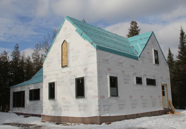
Rob Myers is building a timber-frame house in Ontario, Canada, at a site on the Bonnechere River an hour and a half west of Ottawa. The first installment of his blog series was A Timber-Frame House for a Cold Climate — Part 1.
When assembling the REMOTE shell for a timber-frame building, the first word that comes to mind is “precision” — especially for the framing. As my friends will attest, this job was a perfect fit for me, since I happen to believe that if you are going to all the trouble of measuring and cutting a piece of wood then you may as well measure and cut it to (exactly) the correct length. (You can tell that I don’t do this for a living!)
There are two good reasons to build precisely. The first is that the wall and roof have to be spaced out from the timber frame by 5/8 inch and 7/8 inch respectively to allow the drywall and tongue-and-groove ceiling to be installed by slipping them between the frame and the shell. This allows completion of the outer shell (along with the air/water control layer) while still having full access to the inside wall and ceiling bays for plumbing and electrical work.
There are no worries about re-sealing any penetrations, since all work occurs inside the control layers. The interior finish surfaces can then be relatively easily applied without fitting around posts and braces.
The second reason for precision is that applying the rigid foam and strapping is a challenge in itself without having to guess at the location of every stud or rafter. It is much easier if the framing members are exactly where they are supposed to be and the spacing is maintained over the length of the member by using blocking.
Framing the wall and roof
The wall was constructed using 2x4s at 16 inches o.c. Since the wall is non-structural, the stud spacing could have been 24 inches. But because of the design, thermal bridging is not an issue and I feel that drywall just looks better with studs spaced at 16 inches.
The depth of the wall (3 1/2 inches) was selected so that when the insulation is added to the inside bay, the proper balance of inner and outer insulation is maintained (as calculated for my climate). The top plate of the wall was tied to the timber frame using Timberlok screws and 5/8 inch plywood spacers.
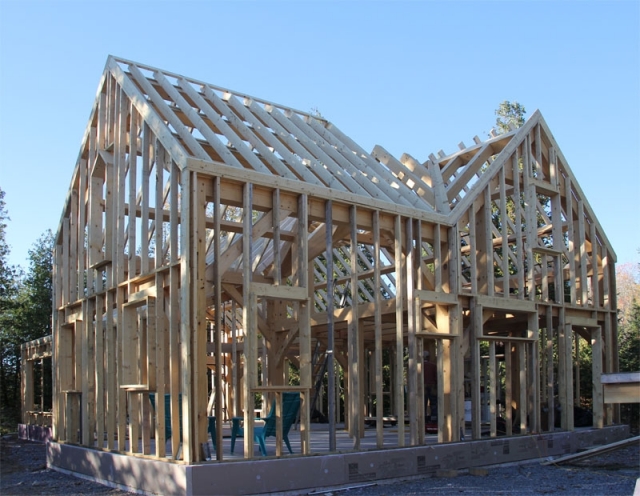
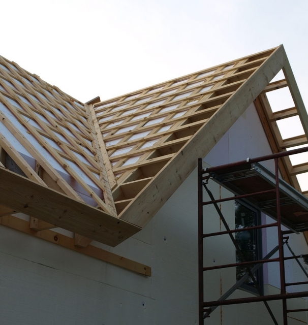
In the same manner, the roof was constructed of 2x6s at 16 inches o.c. (The maximum rafter span from purlin to purlin was less than 4 feet). There were no rafter tails or rake overhangs; everything terminates at the edge of the wall.
The framing was then sheathed with 1/2-inch plywood which tied the walls to the rafters, forming a continuous shell. In my opinion, plywood is preferable to OSB. I also chose plywood because the house would be going through a Canadian winter without a finished roof, and plywood is the material that I thought would best handle the abuse.
As the plywood was installed, I sealed each seam with Siga Wigluv tape. There were no issues with the Wigluv tape adhering to the plywood in the cold — it was near freezing most days — but I always waited for any frost to dissipate before working. Since the tape can be applied to the roof/wall intersection, the air control layer is continuous from foundation to peak.
Innies, outies and in-betweenies
The 2×8 box extensions for the windows and doors were added during the wall framing. I decided to go with in-betweenie windows since this gave a reasonably balanced look from both the inside and outside and resulted in slightly improved thermal performance.
As I mentioned, one of the advantages of self-building is that labor is cheap, so I also opted for a somewhat complex design without worrying too much about the consequences. I chose flanged windows because I felt that they would be easier to install and air seal. The windows were triple-glazed fiberglass and I ordered orientation-specific glazing: solar-block glazing for the west-facing windows, and glazing with a high solar heat gain coefficient (SHGC) for all the rest.
The house design follows passive solar principles, but the best view (and hence the largest window) is to the west, and trees shade one end of the house to the south, so the site is not ideal for passive solar. However, I settled for somewhat compromised performance and kept the view and the trees.
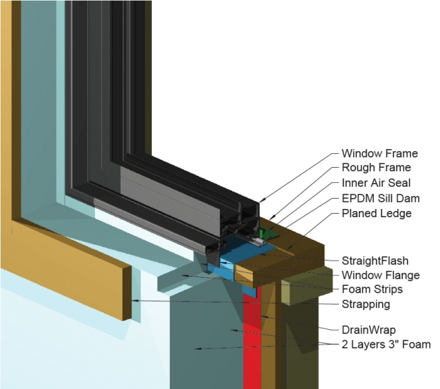
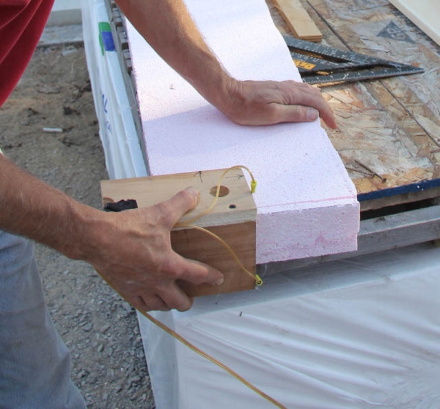
Since the window flange would be in the middle of the wall, the depth of the rough framing box was set so that it also terminated in the middle of the wall. This allowed me to later apply insulation to the outside of the flange to provide a thermal break right up to the fiberglass frame itself. (I used two strips of EPS to make it easier to remove the frame if it was ever necessary).
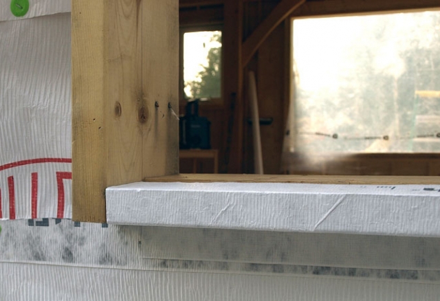
Before assembly of the window boxes, I planed a slope with a small shoulder onto the rough sill so that it would drain to the outside. The rough sill thus has a physical barrier to water intrusion (a small step up). This was easy to do and I think saved a lot of fiddling during the window install.
Air and water control layers
At this point the timber frame is completely enclosed with a plywood box (except for the windows and doors) and the air control layer is complete. I like to ensure that materials are compatible, so I standardized on one manufacturer for the roof and wall water control layers. I applied Tyvek DrainWrap on the wall sheathing and DuPont Roofliner synthetic underlayment on the roof sheathing. The Drainwrap provides a better drainage plane between the EPS and the plywood, although after the house is completed I can’t imagine a circumstance where this would actually be needed. The Roofliner is tough and can be exposed to sunlight for six months. It worked well as an exposed roof surface over the winter.
As mentioned before, I try to build systems that have redundancy. With taped seams, the DrainWrap and Roofliner resulted in a second complete air control layer as well as a water control layer.
Both materials were applied shingle-style, from sill to peak. The materials were fastened with cap staples, and then all seams were taped using Tyvek tape. I taped over the cap staples in some areas, but this was a mistake: the tape tended to lift when the weather got severe, especially on the roof.
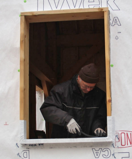
The detailing around the window boxes was pretty much standard. I used DuPont FlexWrap and StraightFlash with proper overlapping technique, tying the window flashing into the DrainWrap. The sill flashing was wrapped completely around the box so that it ended at the inside edge of the window. The windows were then installed using silicon caulk, and the flange and head were taped using StraightFlash. I used cap staples to ensure there was a drainage channel at the sill. The house went through a very long and cold Canadian winter in this unfinished state, with only minor leaking through a few of the cap staples.
Installing rigid foam on the walls
I would have to say that the thought of cutting and applying multiple layers of rigid foam, followed by driving very long screws through the strapping and foam and into a 1 1/2-inch-wide framing member, filled me with some trepidation. I was not exactly looking forward to the task, to say the least.
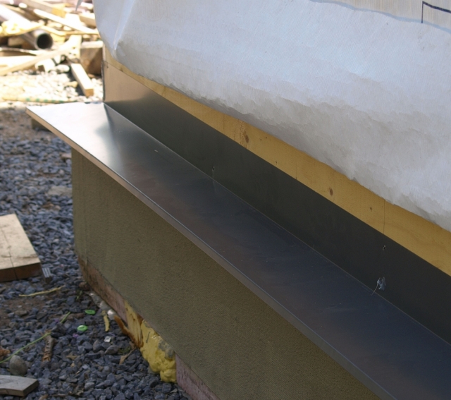
Metal sill flashing was applied to the perimeter and sealed to the base of the wall sheathing using pest-block foam. The flashing offers physical protection to the top edge of the slab foam and the bottom edge of the wall foam, and it ensures that any water is diverted past the edge of the slab.
The first job was to get the rigid foam. I tried to use recycled foam, but couldn’t find a source in Canada that could provide the quantity necessary. Trucking recycled foam from the U.S. wiped out any cost advantage (not to mention any environmental advantage).
In the end, I ordered 4×8 sheets of 3-inch EPS from a local manufacturer. Because I needed a large quantity, the price was almost the same as used material. I also bought the foam a year early, thinking that most of the shrinkage would occur before I used it. The sheets did shrink about 1/4 inch, but I couldn’t find any actual data on rates of shrinkage so I’m not sure whether this was a useful strategy.
I worked out the cuts and the sequencing for application using a 3D drawing program. The foam was cut on the ground and placed without further adjustment (an added advantage of precision building).

I built a very inexpensive hot-wire foam cutter table and a few hot-wire angle cutters to enable accurate cutting of the foam without foam dust. (I discovered that I have a severe sensitivity to the dust and I now try to avoid it at all cost).
The table has a 2×4 frame with an OSB top. (Originally, it was a concrete form.) The arm has to be reasonably stiff. I built mine with a 2×4 column and 1×4 strapping. The arm is 28 inches long; this allows me to cut a 4’x8′ foam sheet into any width. The cutter is nichrome wire from Jacobs Online. One end of the nichrome wire attaches through a hole in the table to a screw connector, while the other end wraps around an eye bolt.
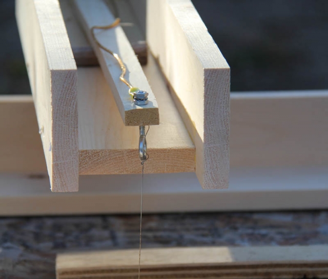
The thinner strip of wood on the top of the gadget provides tension on the wire when it is heated (attach the bottom of the wire, press down on the strip, and attach the top of the wire).
The power is provided by a 50-watt 12-volt halogen transformer. I used a Variac to fine-tune the temperature of the wire, but my guess is that a decent dimmer would work just as well.
The fence has a single screw at one end and pivots to adjust the width of the cut. When I make an adjustment, I just screw the other end of the fence to the tabletop. Not pretty, but it works!
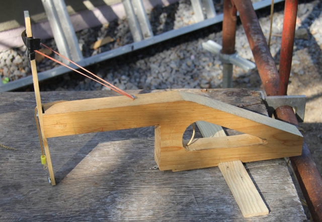
The second cutter is for flush cutting the foam on the corners after it is installed.
The third cutter is for cutting a bevel on an edge (two scraps of wood with the wire screwed across the end so that it cuts the desired angle when moving along the edge of the foam). All just plug in to the same 12-volt power supply. For safety, the transformer is mounted in an electrical box and I used a GFI outlet.
The cutters allowed me to rip the 4×8 sheets while maintaining a perfectly square edge as well as cutting angles to match the slope of the flashing at the sill and the valleys.
They allowed for better quality work in less time; and aside from providing ease of installation, they almost entirely eliminated the use of spray foam to fill gaps. Spray foam is messy, expensive, and requires more work while up on the roof. (I do as much work as possible on the ground — I am not as young as I used to be!)
The cutters also allowed for some details that I would not otherwise have attempted. For example, I wanted to insulate the flanges of my “in-betweenie” windows but still allow for removal of a window if that ever became necessary. (I’m trying to be kind to future generations). I was able to custom-cut foam “flange covers” that friction fit around each window; these flange covers provide continuous insulation to the edge of the frame.

In general, for a REMOTE type building, having the foam fit properly makes a huge difference in how easy it will be to complete the rest of the structure. Roof sheets were cut on the ground and then simply assembled, with almost no spray foam. The rigid foam for the roof valley was cut with a bevel for a tight fit, and as a bonus this also resulted in offset seams. (However, I did have to first hand cut the full sheet using a fine-toothed saw).
For me, the small amount of work required to make the hot-wire cutters more than paid off. But for other builders, the usefulness of these tools will depend on how much foam the project requires.
Securing the rigid foam to the walls
The first 3-inch layer of rigid foam was fastened to the wall using one or two 3 1/2 inch screws and Wind-Lock washers. The second layer was fastened using longer Headlok screws, again with a Wind-Lock washer.
The screws for the first layer are embedded by the next layer, so I didn’t bother removing the first-layer screws as I went along. However, the second-layer screws were removed as I added strapping, since they were thermal bridges and served no useful purpose after the strapping was installed. The holes were filled with a shot of spray foam.
Although not technically necessary, I covered the rigid foam on the walls with a layer of Tyvek housewrap. This primarily protects the foam during the rest of the build. But it also offers a first line of defense against water intrusion. (It’s cheap insurance).
The 1×4 strapping on the walls provides ample bearing on the foam, so there is virtually no compression unless the screw happens to be at an edge (such as near a window). In general, the screw will actually strip out of the wood before there is a lot of visible compression (which is a good reason not to try to countersink the head by overdriving).
The strapping was installed 16 inches o.c. using a 9 1/2-inch Headlok screw that penetrates through the foam and into a stud. The screws are driven in a slight upward direction (about 5 degrees off horizontal) to help prevent settling of the strapping when the siding is applied.
Each piece of strapping was marked from the drawing for stud location and then pre-drilled using a simple jig to set the angle. The hole is also countersunk so that the screw head does not interfere with the installation of the siding. (Countersinking the screw by over-driving it will cause wavy strapping or a stripped screw hole).
If a screw needs to be reset, the original hole was filled with spray foam. Note that different screw patterns will be necessary for different outer wall weights and foam thicknesses.
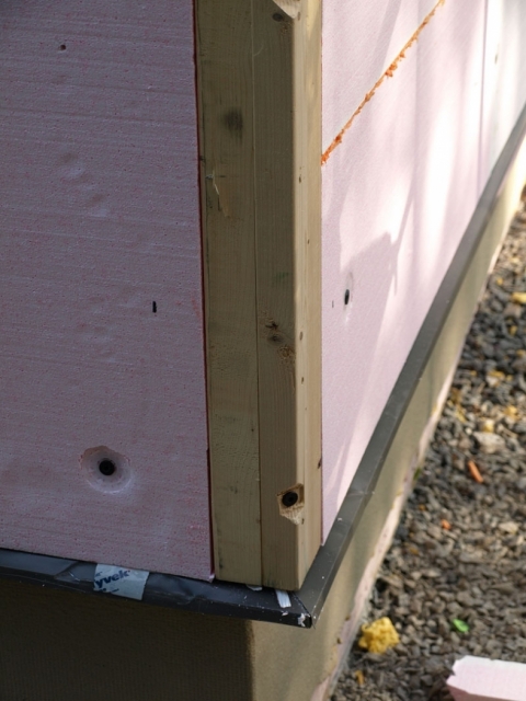
The corners presented an interesting problem, since there is nothing behind the rigid foam to screw to. Typically, two 10-inch-wide pieces of 3/4-inch plywood are used to form the corners, and these are held in place by screws near the edge driven into the corner studs of the wall. I worked out a slightly different method using 2x4s sunk into the foam and screwed through the diagonal into the corner studs. The 2x4s float on a channel in the foam, so the foam corners had to be precise.
This method allows for firm attachment of the corner and each piece of strapping can then run continuous to the corner, which I feel improves the strength of the assembly.
Rigid foam on the roof
The rigid foam on the roof presented different challenges than the rigid foam on the walls. The total foam thickness is greater (9 inches vs. 6 inches) and the strapping consists of 2x4s on the flat, not 1x4s. In addition, in my design the eaves have to be joined to the strapping and installed at the same time. So the whole process is a little more complex.
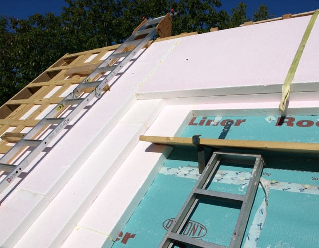
The rigid foam itself was installed in pretty much the same way as for the walls, except there are three layers rather than two. The fit at the eave and rake edge of the roof has to be reasonably accurate so that excess foam doesn’t interfere with the installation of the eave and rake overhangs.
Because the bottom of the eave also rests on foam, I was worried about sagging or the roof becoming uneven as it was assembled. I decided to use continuous 2×4 strapping from the ridge to the soffit with the eave pre-built on to the end of the strapping. I pre-cut and assembled each eave extension and then joined it to the strapping. As an added bonus, the eave assembly then keyed to the edge of the wall, so it actually made assembly a little easier.
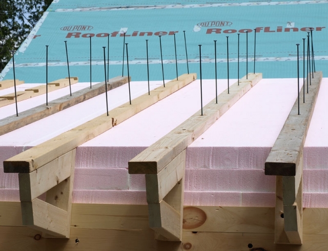
As with the wall strapping, each screw was predrilled and countersunk using a small jig to ensure that the angle was consistent and the hole was straight. Predrilling the strapping was especially important for the roof, because the strapping and foam are both thicker. If you simply try to drive the screw without a pilot hole, then the slightest variation in grain direction will move the screw off axis and it will miss the rafter. I also inserted all screws before lifting the piece to the roof — it is much easier to work on the ground whenever possible rather than hanging off the roof.
This is a cold roof (ventilated) design, so the strapping had to run from top to bottom in order to create a ventilation channel. This meant that the strapping follows the inner rafters which in turn meant that warp and twist of the strapping created major problems when I tried to hit a rafter with the screw. A small twist of just 3 degrees would mean that the screw would miss the rafter (assuming everything else is perfect!). To minimize the problem, I rejected any strapping that was obviously twisted or bent. As it was applied, each piece of strapping was screwed first at the top and then the bottom to flatten it. I paid attention and adjusted for any twist when driving the second screw.
If there was a warp in the strapping, I snapped a line from center to center before installing the piece. After a screw was installed in each end, the center was pulled into the correct position, as judged by comparing the screw hole to the snapped line. The rest of the screws were then driven, and usually these lined up perfectly. Only about 5% of the screws missed on the first attempt.
If a screw did miss, it was fairly obvious. Trying to adjust and re-drive a screw without removal is difficult. (The screw tends to bend and follow the channel in the foam). It is easiest to just remove the screw, re-drill in a new location, and reinstall. The original hole is then filled with a shot of spray foam.
To ventilate the valleys, I used lattice-type strapping to allow air movement through to the ridge.
The addition of the rake extensions was pretty much standard building practice, but I did make use of continuous lattice type strapping to strengthen the overhang.
One other detail that may be of interest was the installation of an air-sealed insulated metal chimney support for the wood stove (available from ICC Chimney). A typical chimney collar and flashing arrangement is not even remotely airtight, and there is thermal bridging due to the clearance necessary for the insulated pipe component.
Finishing the outer roof
The rest of the roof was straightforward. A layer of 5/8-inch tongue-and-groove plywood was installed. Henry Blueskin rubberized membrane was used on the eaves, valleys, and rakes. This was followed by a layer of roofing underlayment. (Any roofing underlayment approved for metal roofing would be fine here, but I used the DuPont Roofliner since I had lots on hand). I then installed a hidden fastener metal roof.
I have been working on the inside of the house this winter without any of the inner insulation installed, and it is still easy to keep warm with a medium-size wood stove. I’m looking forward to seeing how the house performs when it’s finished.
Rob Myers’s previous blog was A Timber-Frame House for a Cold Climate — Part 2.
Rob Myers has worked as an analytical chemist, high-tech manager, and purveyor of fiery foods, all of which served to support a lifelong love of woodworking and building (not to mention a wicked tool habit). He is currently on a (possibly permanent) sabbatical from any real job while he builds an off-grid timber-frame home near Eganville, Ontario.
Weekly Newsletter
Get building science and energy efficiency advice, plus special offers, in your inbox.


33 Comments
EPS and Energy Analysis
Don't have time right now to read every detail. Read your previous articles but don't remember a lot.
Comment: I think you said you couldn't find a lot of data on EPS shrinkage. Don't know if there is data, but there sure is experience that shows it could shrink severely, perhaps negating some of your precision fits.
Question: If you have done any energy analysis/projections, can you post those, including design temperature, heating load, perhaps estimated solar fraction?
Impressive work
Thank you for taking the time to document and photograph your work, tools, and techniques. If this kind of workmanship is done on the shell, I'll be eager to see the finished interior as well.
A+ for the standing seam metal roof.
Q: Why the horizontal furring strips?
EPS and Energy Analysis
Rick,
The specification for the EPS that I used was a maximum 1.5% shrinkage which is a fair bit over an 8' length. I would still rather start off from a good fit to minimize gaps but because the layers are also overlapped, the performance hit due to shrinkage should be relatively minor. Note though that the main reason for the effort put into accurate fitting was to minimize problems with applying the strapping and eave/rake overhangs.
As to energy modelling - it was done almost 4 years ago and the data is not immediately available (it may be easier for me to just re-enter it using a more up to date program). However, I would say that I was not all that interested in meeting arbitrary targets and once I had established a basic design heat load I didn't spend a lot of time with modelling.
As I mentioned in an earlier blog, the timber frame was a given so I was therefore dealing with a fixed size shell of a certain shape with cathedral ceilings. The house orientation was set by the views and there were trees to the South that allowed only partial passive solar heat gain. The shell was as air tight as can reasonably be achieved and other than maximizing floor/wall/roof R value and selecting good windows, there was quite simply not a lot to adjust.
I guess my point is that I didn't obsess over energy modelling. It was useful for guiding me but it didn't control the design.
Andrew,
Thanks for your
Andrew,
Thanks for your comments, my wife is also very interested in seeing a finished interior!
Standing Seam Metal Roof
Chris,
The lattice type furring strips (horizontal/vertical) were the only way that I could think of to provide ventilation to the valley. The valleys themselves are well protected but if there was going to be any water intrusion I was pretty sure that this is where it would happen and I wanted to make sure that it could dry.
@Rob Apologies for not being clear as I was talking about
the horizontal furring strips on the walls not the roof.
Furring Strips & roof
Chris,
The wall furring strips are horizontal so that I can apply reverse board and batten siding (i.e. vertical siding).
Just a further comment on the roof - I also liked the look of the standing seam roof and in some ways it was actually easier to install than regular exposed fastener roofing. It is a light gauge design that was not too much more expensive than regular exposed fastener roofing. However, the valleys etc. were a little trickier to install since everything interlocks and every panel had to be trimmed and folded. However, because the sheets do fold around the eave starter, you end up with a better roof that is less susceptible to lifting or water intrusion.
furring
Rob,
Did you use 3/4" 1x4 for the lattice in the valleys and/or did you dado the 2x4 for the horizontal furring strips?
The detail at the rakes/gables looks a bit different. Do you have any drawings or other details you can post?
With the horizontal furring on the walls, did you dado vertical channels in it? Or are you planning for the rainscreen to be more passive drying rather than an air channel behind?
air-sealed chimney
Rob,
Can you provide a picture of the air sealed chimney you mentioned.....I checked the ICC site and couldn't easily locate it. I'd love to see it as a part of your build and not just a pic from the website.
Thanks,
Brad
Furring
Brad,
Yes to both. I used 1x4's and I dadoed them into the 2x4's. That's what happens after you do a timber frame - everything else (like a series of dadoes) just seems trivial. The whole point was to provide a continuous solid support to the eave/rakes and still allow airflow to vent the roof.
The horizontal furring is not dadoed (although I did use that detail on another building). Reverse board and batten has a natural air channnel that provides a vent for the wall. At the top of the wall I use a strip of Cor-A-Vent to provide the air exit point (it does not vent into the roof).
Air sealed chimney
Brad,
This was discussed in another posting:
https://www.greenbuildingadvisor.com/community/forum/green-building-techniques/59451/installing-metal-chimney-wood-stove-through-spray-fo
In that discussion I mentioned the specific link to the ICC site:
"Here is a link to the US installation manual, the insulated collar is a lot easier to envision using the drawings. The relevant section is part number ERDSI - Insulated Round Support Pge 19"
http://icc-chimney.com/c/icc/file_db/docs_document.file_en/XLUSA-II_2012-01.pdf
Rob
Thanks, Rob
Rob,
The GBA community is grateful for your detailed and helpful answers to questions from readers. Thumbs up!
Thanks Rob
Rob,
I echo Martin's comments. Most appreciated. I didn't see that discussion about the chimney, but have now and it answers my questions for sure!
In regards to the board and batten (B&B) siding? How wide are your battens, or rather how much space is between the boards? I've always installed B&B siding using shiplap (nailed tightly together) and just covered the seams with an additional "batten". The only way I've found that they are naturally ventilated was through the small seams and the wood itself, but that doesn't provide any better ventilation than typical siding. Is there something about the way you apply you B&B siding that makes the ventilation more enhanced?
I would think that there might be enhanced ventilation if the spaces between the boards was gaped quite a bit and then covered with the batten (providing vertical ventilation channels, and ventilation for the horizontal spaces between the furring strips).
I like the idea of the dados, I think it must strengthen the whole assembly.
Thanks again!
Reverse Board and Batten
Glad that I can add something back to the GBA community - I have certainly taken enough away with me!
With reverse board and batten, you essentially have a ventilation space that is almost the width of the wider board. For a good discussion of the options and possible problems:
https://www.greenbuildingadvisor.com/community/forum/energy-efficiency-and-durability/44156/proper-nailing-pattern-reverse-board-and-batt
The dado's in the strapping at the rake made assembly easier and kept the 2x4 thickness for the length of the strapping but since everything was then covered with 5/8" t&g plywood I don't think that it would add a whole lot to the overall strength.
Rob
Thanks Rob
Wow thank you so much. I am plodding down the same road and have decided to build 2 x 6 with 4" EPS exterior and 3 layers on a hot cathedral roof. You have answered so many questions and some I hadn't yet thought of.
Would be interested in the name of the foam supplier as I had already checked out reclaimed roofing and will need a lot so I'm a little worried about supply.
Building in Britt, Ontario North of Parry Sound, lot services are in and foundation next for a self designed 1200 sg ft coach house with living quarters over 3 bays and a loft, 12 12 pitch steel roof and Hardie panel. Faces South with 175 foot sand beach.
Thanks again,
John
Wire cutters and foam glue
I love the creative engineering on the wire cutting tools. Thanks for sharing photos of those.
Your valley laping of the roof foam is impressive. Nicely done.
Curious if you did, or considered, edge-gluing your EPS panels to each other as you installed them.
Also curious if people think that would help address or alleviate possible foam shrinkage issues.
edge glueing foam
Elden,
I'm installing lots of 2 layers of exterior 2.75" EPS foam, and was planning to spray foam in between each layer and also every edge, along with taping the seams with the zip system tape.
I've had lots of discussions with folks about foam shrinkage, and if all those steps are required, or if it's just excessive. I'd love to know if anyone knows of studies that were done to compare the two. On my barn I'm in the middle of building, I've considered doing half of one south face wall with foam and tape, and the other half without and measuring the outcome to compare.
reverse board and batten
Rob,
I missed somewhere that you were doing reverse board and batten. There is obvious vertical ventilation channels with that technique. I've actually done that before and to alleviate the problem with center nailing the wider outside board, we just put thinner strips in the middle to nail through. It kept everything much straighter over time, and definitely reduced the cupping.
Pure Cock-Up
Is this what you call worthwhile information? Her is the link to the REAL Solution https://www.dropbox.com/sc/b9qnk2cyvpv3zap/AAAy_rPiGa04MgaOdZv3Viqaa
and thank you.
Source of Foam
John,
The foam I purchased was from LegerLite (legerlite.ca - Pointe-Claire (Quebec)) and it was ordered through a local lumber yard (LegerLite could provide a name of the closest supplier). Because of shipping cost you may be better off finding a local manufacturer.
Wire Cutters and Foam Glue
Elden,
Thanks for your comments. The hot wire foam cutting tools were pretty simple and very inexpensive to build but they worked incredibly well. The valley cuts were simple to do - just hand cut the sheet at the correct valley angle and then use the beveling tool set to the backing angle. There's no magic - if it's cut at the correct angle it will fit!
I am not an expert on foam (hopefully someone else will join in) but I do not think that edge gluing would help with shrinkage since the joint (and the foam in general) would not have a lot of tensile strength and if shrinkage occurs the joint will just fail. If there is a single layer of foam then shrinkage is a concern. For multiple layers with staggered seams, it seems to me that the loss in performance due to a small amount of shrinkage on each sheet will be pretty small.
Edge Gluing Foam
Brad,
Perhaps you should post a new thread describing your wall and the question regarding the foam and tape. The necessity of taping the foam is dependent on whether the foam is just insulation or whether it has to act as a water resistive barrier, an air barrier or both. It is expensive to tape the seams and I personally would not depend on a tape to foam bond (unless the foam has a foil facing).
Reverse Board and Batten
Brad,
Thanks for the tip about the center strip. Would each wide plank then have 3 nails (one near each edge and one in the center)?
furring nailing and edge glueing
Rob,
How wide is your outer batten? How wide is your inner batten? How wide is the reverse batten space?
I've always liked at least a 1x3 for the middle or 1x10 ripped in equal thirds. Depending on your reverse batten space I'd go 1x4 on the space or 1x6 with a wider more unique spacing. 1x6 leaves some meat to nail to, and provides a larger base for the outer board. 1x10 makes a nice unique outer board.
I'm lucky where I live because there is an extremely large mill nearby, and they have essentially an unlimited amount of varied width shiplap, v-groove, beadboard, and S3S planer offs and it is sold at a ridiculously low price too. So there is lots to choose from.
I try to face nail four times for 1x12, and 3 times for 1x10 & 1x8, and 2 times for 1x6 & 1x4.
It's smart to let the wood sit for a while too unless it's kiln dried, otherwise I found that edges will split out, as the wood can't shrink. (Wood shrinks across grain much more than with the grain.)
Make sure you use a steel cloth on the outer edge of the vent channel (Cor-A-Vent), otherwise squirrels and other such vermin and varmit will chew through it and get up inside.
Furring on Exterior wall
I am sorry to bring this up again, but the horizontal furring bothers me. Will rain water or any moisture collect on the upper edge of the furring and cause it to rot? We have always kept the furring vertical allow for drainage. We had horizontal and vertical battens covering the joints of painted homasote panels on the exterior of our garage when we moved in. The horizontal battens had rotted to a greater extent than the vertical. Upon removal of the panels the entire wall including the 2x4 framing and interior drywall had to be replaced from damage caused by water leaking into the garage from the battens. Excellent article and appreciated sharing your innovations with us.
Response to Paul Austin
Paul,
Were the horizontal battens on the exterior side of the Homasote or the interior side of the Homasote?
If they were on the exterior side of the Homasote, it's no surprise that the battens (a) rotted and (b) allowed water to enter the horizontal seams of the Homasote.
If they were on the interior side of the Homasote, did the builder remember to install Z-flashing at the horizontal seams of the Homasote panels?
Paul
I think it is pretty climate dependant. Here in the PNW I wouldn't do it (nor would our code allow it). But in areas where even if bulk water intruded and wet the strapping it still had lots of drying time, I don't see it as much of a problem. It's worth remembering that only the battens are touching the furring.
Horizontal Furring
Thanks Martin and Malcolm for your comments and Paul for bringing up the issue. I would say that I didn't really consider this when I designed the house - the furring had to be horizontal for vertical siding and so that's what I used. Because the walls are well ventilated I can't see that the furring would ever be wet for an extended period (in fact with properly installed siding I can't see it ever being wet period - perhaps some damp areas after a heavy, wind driven rain, but not wet). At any rate, I don't consider this a big risk to the structure since it will just dry.
Malcolm - If you have time could you briefly describe how you would do vertical siding in the PNW?
Hey Rob,
I'm thinking of doing the same thing on the other side of Ottawa! Can you give me a list of the books that were most helpful to you for this project?
Hi Rob,
I happened to read all three parts to your timber frame building experience, as I took the same timber frame course in Perth with Jason Gibson, and I plan on constructing the same structure from the Week One as a bunkie on my waterfront property on Manitoulin Island.
I was intrigued by how you went about constructing the wall shell around the timber frame itself. I, myself, am trying to envision how you did everything, especially those sections that didn't have photos. I want to make sure that I do everything correctly on a smaller scale before possibly moving up to a larger scale build. Screwing up on a smaller scale is much easier to swallow.
I'm not sure how to install the drywall without damaging it after the shell has been constructed? I was of the impression that the drywall would be placed, and then the wall built outside of that? The same thing goes with the cathedral ceilings. Would it not be easier to install the tongue and groove boards on the rafters first, then construct your roof after? I'm somewhat confused.
At any rate, the three part series on the build was certainly information added to my knowledge base going forward. I hope that my project will turn out as well as yours. Cheers!
Hi Rob,
On the integration of your Tyvek air barrier with your window bucks: did you tape and seal the entire interior and exterior of the buck?
I'm also curious how you flashed the window sill out to and over the siding, over the exposed foam strips?
Thank you!
Rob,
Looks like a very cool project. I am curious what you did with the EPS around the stovepipe that was put in. Did you just cut a 2in clearance space around the pipe or did you do something different?
Log in or create an account to post a comment.
Sign up Log in