
Image Credit: Dwight Holmes
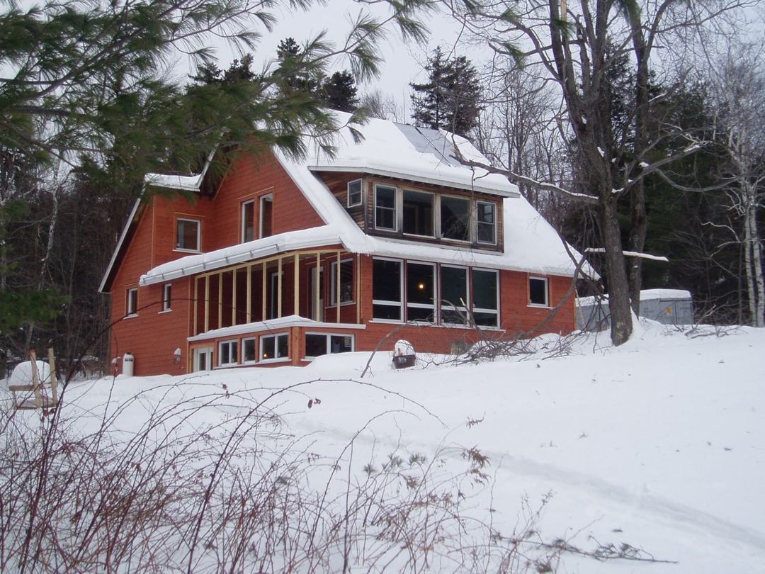
Image Credit: Dwight Holmes The completed project. The house now has more than 2.5 times the conditioned space while using only half the energy for space heating and domestic hot water as the original residence. Note the solar water panels (upper right) and the nice even layer of snow on the well insulated roof.
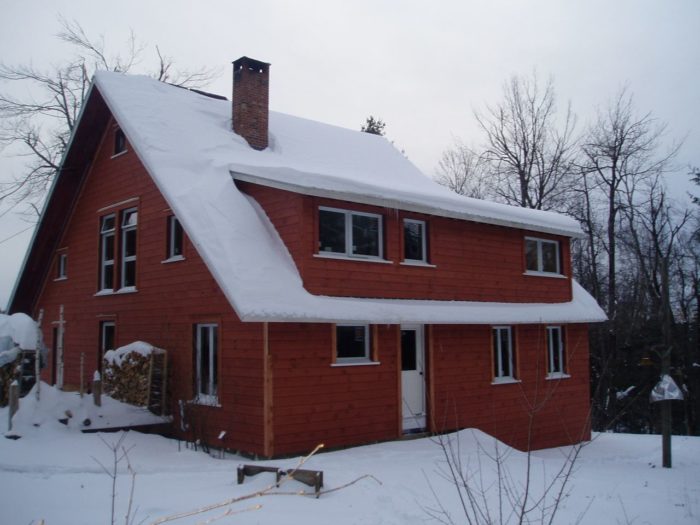
Image Credit: Dwight Holmes The rear of the home is just about done. Note the deep sills on the high-performance windows (with triple-paned, argon-gas-filled, double low-e glazing).
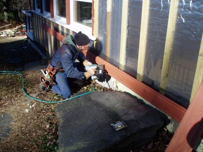
Image Credit: Dwight Holmes The housewrap is the continuous drainage plane behind the rigid foam. This super-protects the weather-resistive barrier but can mean some tricky connections to exterior flashing at penetrations.
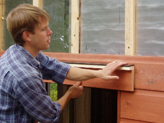
Image Credit: Dwight Holmes A nifty detail at the bottom of the rainscreen. The insect screen runs up behind the first course of siding and is then folded down and trapped by the second course of lap siding. The excess is trimmed.
Image Credit: Dwight Holmes Dwight sets up the door head flashing cap. The cap is integrated with the furring strips and rigid foam. (A layer of housewrap installed behind the rigid foam acts as the weather-resistive barrier).
Image Credit: Dwight Holmes A new sunroom. The old screened porch was converted to a sunroom with radiant floor heat (zoned separately and set for 55°F). At night and on cloudy days, the windows and doors that separate the sunroom from the rest of the house can be closed to isolate the room from the main conditioned space.
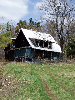
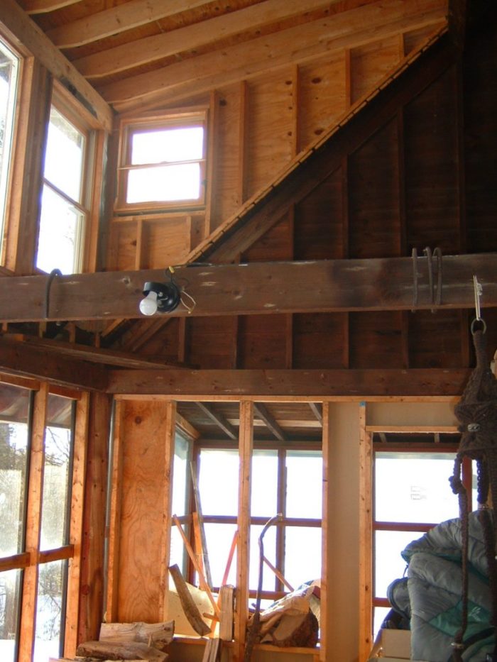
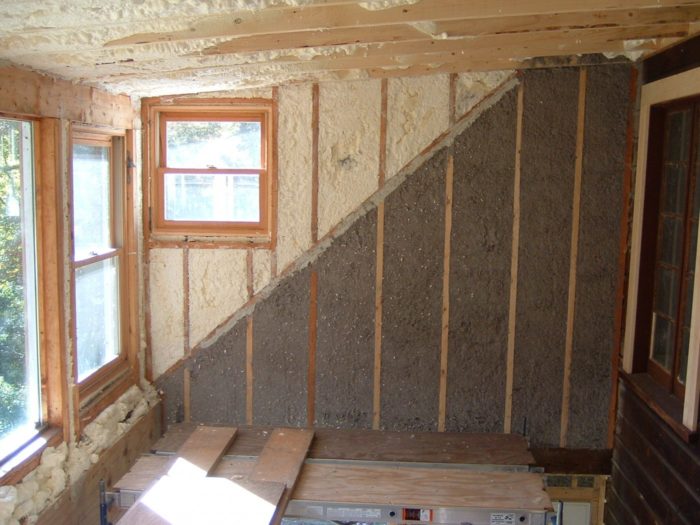
Image Credit: Peter Yost This is how the original sunroom west wall looked--just open-frame as many single season cottages are.
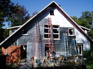
Image Credit: Doug Snyder The west wall of the sunroom after insulation. Note that since the dormer was not reclad on the exterior, a higher R-value spray foam was used as cavity insulation whereas the west gable wall, which was reclad, has the cellulose for cavity insulation and also 2 two-inch staggered layers of exterior rigid polyisocyanurate insulation.
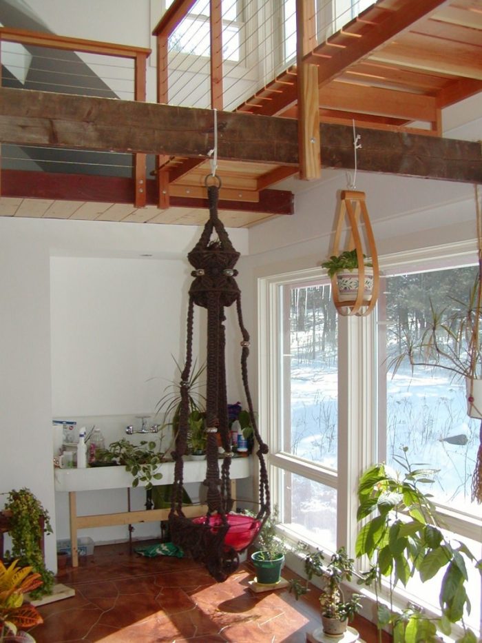
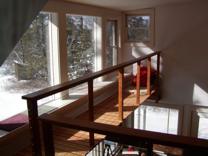
Image Credit: Doug Snyder This catwalk is the "second story" of the sunroom. The deep walls of the energy retrofit make for great window seats, which Mary and her cats use quite a bit.
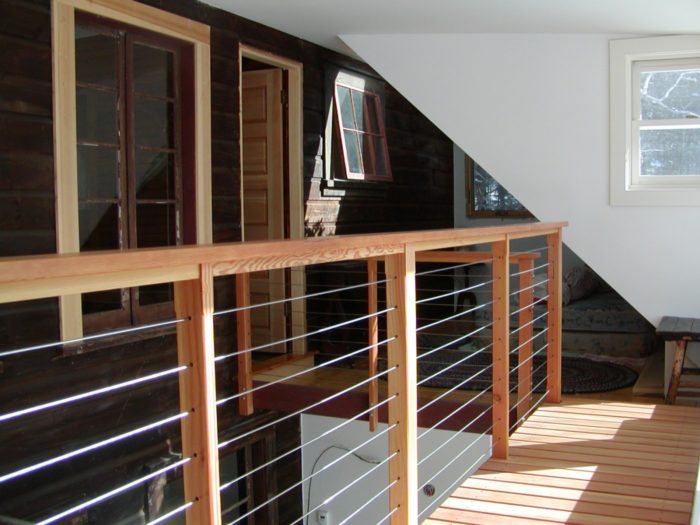
Image Credit: Peter Yost Reused or original windows and some doors can isolate the sunroom from the rest of the conditioned house. The builder did a really nice job of combining original and new wall finishes throughout Mary's home.
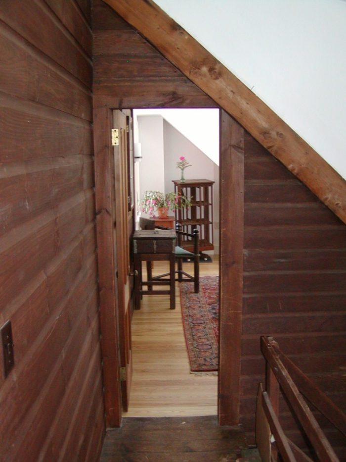
Image Credit: Peter Yost Mary remembers this upstairs hallway as a dark, ugly "scurry" space; the original roof line (right where the wall finish changes) was relieved by a large shed dormer. Mary now lingers in this hallway to get to her bright and airy sitting room.
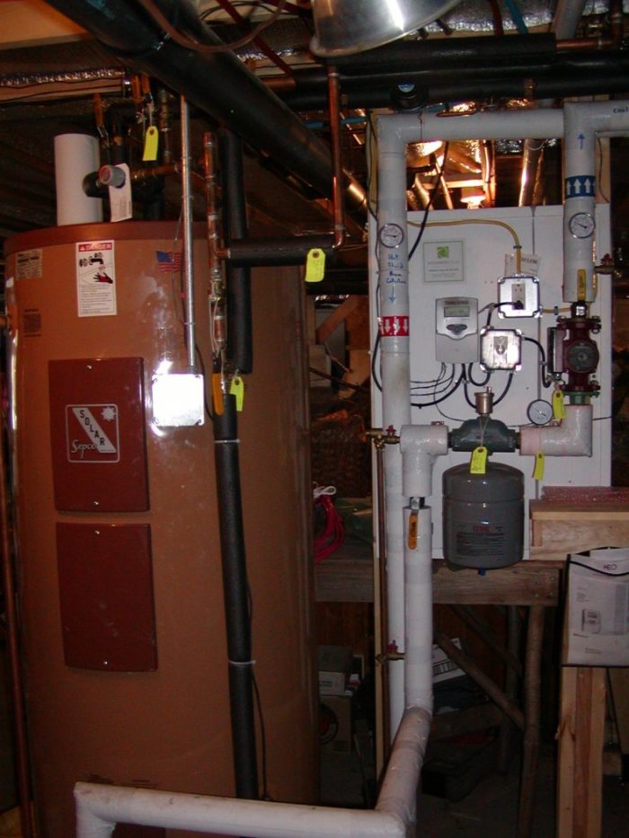
Image Credit: Peter Yost The control center for the space heating and domestic hot water systems. The controls integrate the operation of the wood boiler, the solar hot water panels, the 120-gallon domestic hot water tank (left), and the 600-gallon heat storage tank (just off to the right and out of this picture).
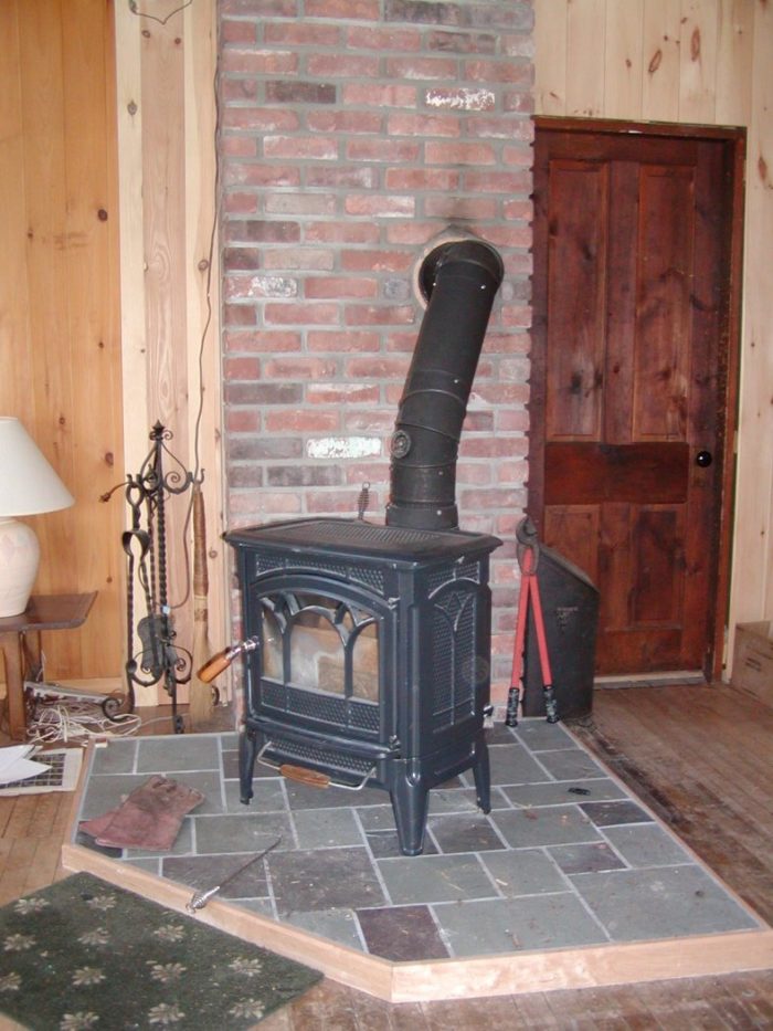
Image Credit: Peter Yost The “take-the-edge-off” heating system is centrally located on the first floor. Mary uses this small wood stove for backup heat during power outages and during the shoulder seasons.
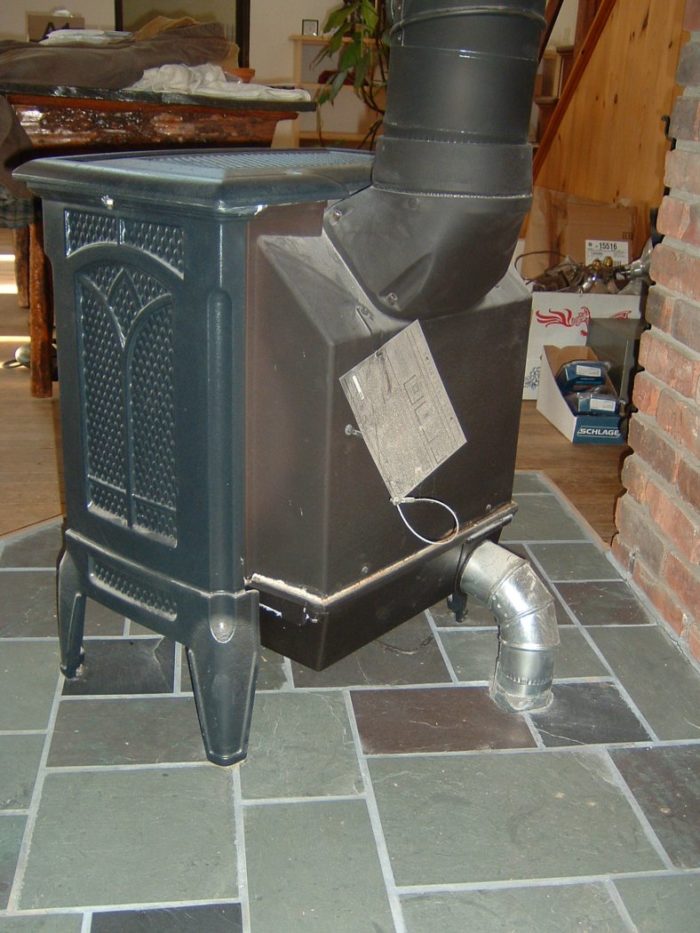
Image Credit: Peter Yost Not easy to find, but this is a sealed combustion 81% efficiency wood stove, the Craftsbury by Hearthstone. Note the dedicated outside air supply duct.
Image Credit: Doug Snyder Doesn't every Vermont deep energy retrofit come with a 1966 white BMW R-60? Mary bought this new and still rides it each summer.
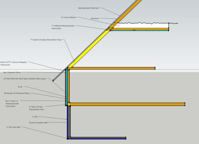
Image Credit: Peter Yost More than one insulation type. The contractor used a wide variety of insulation products — closed-cell spray foam, open-cell spray foam, XPS rigid foam, polyiso rigid foam, and cellulose. The properties of the chosen insulation materials were matched to the thermal and moisture performance requirements of each assembly.
Image Credit: Toshi Woudenberg
A deep energy retrofit turns a summer cottage into a snug full-time residence
By Doug Snyder
In 2008, contractor Dwight Holmes went to work with homeowner Mary Sargent on a deep energy retrofit of her 1917 “Tea House.” Nestled into a hillside apple orchard in Vermont, the building was originally constructed as a private, summer-only, communal dining and entertainment hall with living quarters for servant help. The house included many doors and large single-pane French windows to allow summer breezes to pass through the building. While this is ideal for the summertime, maintaining a livable temperature indoors during Vermont winters was a challenge.
Mary (and her dog and two cats for mouse patrol) love wood heat — but also hoped to buy, haul, and stack less wood each season. Thermal comfort was also an issue. Many times during the winter, Mary would return home at the end of the work day to a house that was 45°F inside, with the wood stove fire long gone. The existing building had mostly bare 2×4 stud walls; the only insulation was fiberglass in the walls of the core rooms of the building on the first floor. On more than one occasion, ice dams formed large enough to break off and smash basement windows. The project’s primary goal was to expand the thermal envelope of the building to include all of the occupied floor space — and to do so in a super-efficient way.
Energy modeling and budget
Although Mary had a healthy budget for her deep energy retrofit, Dwight knew that the cost of all the energy upgrades would quickly add up. To optimize the design for energy efficiency, energy consultant Doug Snyder used Energy 10 software, a modeling tool well suited to passive-solar projects measuring under 10,000 square feet.
Snyder ran about 20 simulations to compare the energy performance of different building modifications and to explore diminishing returns. The energy modeling results established the optimum combination of dollars spent for energy saved. The plan called for aggressive air sealing, R-20 insulation on the foundation walls, R-40 insulation in the upper story walls, R-60 insulation in the roof, and triple-pane low-e windows.
Energy 10 modeling projected heating savings of 81% over an estimated baseline. (Determining the baseline for the project was difficult, however, since only about half of the home was insulated and the wintertime interior temperature was kept unusually low and would fluctuate greatly.)
Balancing passive and active solar
The site enjoys good solar orientation and access, so solar power was an early consideration. The existing structure had a large sunroom with two stories of south-facing glazing. The sunroom seemed to offer a great opportunity to capitalize on wintertime solar gain.
Since the green building consultant, general contractor, and solar thermal and heating system designer were all concerned about temperature swings in this area, they decided to insulate the two-story interior partition wall separating the sunroom from the remainder of the house. Operable French windows were reused and installed in the upper portion of the partition wall. As the sun room heats up in the wintertime, the French windows can be opened to share space heat generated by passive solar gain with the rest of the house. While the SHGC of the south-facing glazing was not optimized for solar gain, the sun room still heats up to 80°F on sunny winter days. A thin floor of stained and detailed concrete was poured in the sunroom to increase the room’s thermal mass.
Building assemblies designed and specified for durability
I think Dwight and I did a decent job of looking at vapor barriers and condensation and drying potentials as we worked out the wall design. I even had some email dialogue with John Straube at BSC regarding drying potential of wood components if spray foam were used as the cavity fill coupled with polyiso exterior foam board. I think eliminating the need for an interior vapor barrier by using exterior sheathing insulation is elegant.
High performance heating with wood stoves?
The original heating system included two wood stoves: one large stove in the basement and a second stove in the main living room on the first floor. The new heating system consists of a wood boiler in the basement and two flat-plate solar hot water collectors.
Both heat sources feed a large built-in-place 600-gallon water storage tank that is insulated to R-60. The domestic hot water tank (with a backup electric element) pulls water from the larger 600-gallon tank.
When the thermostat calls for heat, the wood boiler heats the home directly; otherwise it dumps heat into the large 600-gallon tank. Because of cost constraints, a Marathon brand wood boiler (with an efficiency of around 70%) was chosen. A more efficient (80%+) but more expensive Tarm boiler was a budget-buster.
The multiple-zone heat distribution system consists of radiant tubing under the first floor and baseboard radiators on the second floor. The radiant floor seemed ideal for the first floor because most of the space has a high cathedral ceiling.
There is also a small sealed-combustion wood stove in the living room for backup heat in case there is a power failure and the boiler and associated pumps cannot run. Since the tight home has less natural air infiltration than it used to, some effort was made to find a sealed-combustion wood stove so that backdrafting would not be an issue.
Careful air sealing and superinsulation helped the heating system contractor design a system that was smaller that what would have been needed had conventional insulation levels been used.
It’s all about a general contractor who listens
If you ask Mary what the most important aspect of her project was, she will say without hesitation, “Dwight. He was a real professional, always listening. And he knew just when to rein me in.”
This was a complicated project for a homeowner with a lot of vision. Dwight got the technical details right but also helped Mary along with the difficult process of translating a vision into a real project with a budget. Green remodeling can be as much about business sense as it is building science.
Weekly Newsletter
Get building science and energy efficiency advice, plus special offers, in your inbox.
Lessons Learned
As is typical during the first year of operation, the boiler and solar hot water systems had some glitches. The solar system needed to be tweaked; a faulty check valve in the piping circulated warm water to the cold panels at night for several cold months during the heating season. This meant that the heat gained during the daytime by the solar panels, and perhaps even a some of the heat contributed by the boiler to the large hot water storage tank, was lost at night. The wood-fired boiler also required a modification to the control for the return water temperature to the boiler. The first winter’s fuel consumption exceeds what would have been used if the system had not had these initial problems.
During the first winter, the basement was (surprisingly) just as warm as the upstairs occupied space, even though no intentional heating elements had been installed there. Since this space is not occupied, it would be more efficient to save this heat for the upper occupied floors. Two suspected causes for this excess heat are waste heat coming off of the boiler and radiation downward from the radiant tubing installed under the first floor (in the basement ceiling). Better insulation underneath the tubing could help this situation, and this will be considered for future work.
The ERV began making some noise as construction was wrapping up. Metal components on the interior fan cages were frosting up and the increased friction was causing the noise. This was a surprise since, ERVs are less likely to freeze than HRVs. After calling the manufacturer and doing some troubleshooting, we figured that the freeze-up probably occurred as a combined result of very cold winter temperatures and moisture-of-construction in the home (recently installed damp-spray insulation and the drywall compound applied to all of the newly finished interior walls). The frosting over of components inside the ERV did not recur throughout the remainder of the winter.
Mary wishes she had known more about renewable energy systems at the very start of the project. “It has taken us the better part of two heating seasons to work out all the mechanical issues,” Mary says with just a hit of a lament. “But today, the system works much better and I understand a lot more about how to get the most out of the wood boiler.”
General Specs and Team
| Location: | Marlboro, VT |
|---|---|
| Bedrooms: | 3 |
| Bathrooms: | 1 |
| Living Space: | 2780 |
| Cost: | 88 |
| Additional Notes: | Energy-related components: $107,000 |
Contractor: Dwight Holmes Energy consultant: Doug Snyder - DS Greenbuild, LLC Mechanical contractor: Andy Cay, Integrated Solar Applications Building Performance and Insulation contractor: Keith Abbott, Thermal House
Construction
Back-vented wall cladding
Metal roof cladding
Energy Specs
Air tightness: 2.8 ach50
Foundation walls: R-10 XPS
Above grade walls: R-40 (2 - 2-inch staggered rigid polyiso + 4" spray cellulose)
Roof: R-60 (2" closed-cell spray foam + 14" spray cellulose)
Windows: Bonneville triple-pane (U-0.26; SHGC = 0.34)
Wood boiler: Marathon 70,000 Btu/hr
Indoor Air Quality
Mechanical ventilation: Renewaire 200 ERV
Interior hygrometers
Green Materials and Resource Efficiency
Reused French doors
Durable exterior claddings (back-vented and rainscreened)
Alternate Energy Utilization
Solar hot water: Gobi 410 Heliodyne (43,000 BTU/clear day) flat-plate solar collectors


12 Comments
Building Performance
I can't tell by the article if all of the existing building envelope was superinsulated and airsealed, if so, 2.8 ach50 is disappointing. Building perfomance will not be stellar with 2.8 ach50, the ERV may not be needed but for 10 or 15 minutes per hour.
aside Doug - what is the
aside Doug - what is the maximum air changes for hour to maximize the use of a HRV or ERV?
Natural air change
If this house is 2,780 sf, my math tells me the volume is about 24,000 cubic feet. 2.8 ach50 divided by 17 or thereabouts is a natural air change of .165 or 66cfm. The point I am making is a fair amount of the ventilation air for this house will be in the form of infiltration and will not have the heat recovery associated with the ERV. Granted this is a retrofit and it is hard to tighten up existing housing, my own home after some air sealing is right around 3ach50, but I have not addressed the walls, they are original.
I believe a lot of new homes are over ventilated, the HRV or ERV humming along on low speed and a good bit of infiltration thrown in. Soon enough as winter progresses the humidity in the house drops in the 20% range and the humidifier kicks in. This is poor building to say the least, 1.5 ach50 is very realistic for new construction and 1 or less in attainable with a clean design.
Building Performance - Infiltration Rates response
Great to see the discussion here. I knew when I saw the title that was chosen for the case study that it would grab some attention and potential critique, so I think it is a great opportunity to dive into infiltration issue a bit. I think “disappointing” is a bit strong for characterizing the infiltration rate of this project, but I do agree that even better air sealing is possible.
When construction was in process, we did have access to most of the walls from the interior and exterior, with the exception of the kitchen and bathroom downstairs which had been sheetrocked already. All other surfaces lacked sheetrock and framing was exposed. So, yes, there was a lot of opportunity for air sealing and insulating, with the exception of possibly some week points behind kitchen and bathroom cabinets, although those could have been addressed with an air barrier detail on the exterior. Because of the complex design as you can see somewhat in the photos, it was not always possible to air-seal all wood-to-wood connection points, especially when compared to new construction. While an exterior air barrier can mitigate losses through structural details, I feel more confident when I can stop infiltration in several approaches (drywall to framing, penetrations, wood-to-wood connections, sheathing, etc….). That way if one system is failing, there is another to back it up.
At the time of design, in early Spring 2008, I was targeting a natural air change rate of 0.15. I thought that was pretty decent. Manual J published by the ACCA, which is the default calculation format for sizing residential heating and cooling equipment, lists homes between 2001 and 3,000 sf as tight at 0.15 natural air changes per hour. For comparison, 0.85 NACH is considered loose. Also, the simulation software I use, Energy 10, relegates infiltration units to either ELA (effective leakage area) or natural air changes per hour. So my thinking was more along the lines of natural infiltration rates and a target of 0.15 NACH. When we tested out the home, the insulation contractors calculated a natural infiltration rate of 0.13 and we felt pretty good about the performance. This number does include the basement though as part of the total volume, which is not always standard practice and tends to favor better infiltration performance numbers, but the basement does have windows, walkout French doors, and is half used for gardening. So as far as being “occupied” space, the argument can be made for it.
One of the weaknesses that I am now aware of with using natural air changes per hour is the decision or guesstimation process of choosing an N factor. A more absolute approach to specifying air-infiltration rates, is using ACH50 (air changes per hour at 50 Pascals), or CFM50 per sf of surface area which relates closely to ACH50 through conversion calculations. So, if I had been more aware of using infiltration rates at a more absolute tested pressure (50 pascals) instead of the more fuzzy natural infiltration rate calculation at the time, I would have specified accordingly.
Knowing what I know now, I think I would have targeted and 1.5 ACH50 maximum. Passive house standard is 0.6, and is very difficult to achieve even in new construction with people who know what they are doing, so we have to give ourselves some allowance for the challenges of existing buildings.
David Keefe wrote an article in Home Energy Magazine, I believe back in the 90’s, titled “Introduction to Blower Doors” which you can find archived at their website. It’s a nice overview on infiltration and testing details. He cites that homes with “less than 5-6 ACH50 are quite tight and those over 20 are quite leaky.” So, within that context also, this home performs decently as far as being called “tight.” But, obviously the article is now a bit dated.
Another well respected consultant up here in the Northeast who is famous for his super-efficient projects, Marc Rosenbaum, recommends a minimum tightness for a superinsulated home to be 0.10 CFM50 per sf of surface area and desirable target of 0.05 CFM50/ssf. For comparison, a leaky old home could clock in at 1 CFM50/ssf. Square feet of surface area (ssf) in these instances is the surface area of all interior surfaces on all six sides (or more in our case) of the building, including the basement.
Our total surface area is approximately 6,700 (some exterior dimensions used), and with a CFM50 of 1150 (the latest test-out for the building), this yields 0.17 CFM50/ssf. So, in this case, yes, we did miss the minimum target according to Marc’s guidelines.
In case folks want to run other numbers for this home, volume excluding basement is 19,798cf, and including the basement is 30,008cf. Square footage of occupied space is probably more accurately 2,532 sf. This excludes the “to be enclosed” porch which is actually exterior to the thermal envelope but was included in the square footage stated in the building summary in this case study. General advise, be careful with units. It's very easy to confuse yourself with CFM50/ssf, ACH50, and NACH. Sometimes the numbers are similar, even if the units are different.
In conclusion, I think while this home falls inside what was previously considered the “tight” category and what is still considered tight according to Manual J, at the same time, the concept of tight, especially for existing home retrofits, is evolving quickly and becoming stricter, which is a good thing.
air change rates
Some more opinion/info -True, the natural ventilation can equal your targeted supply cfm rate, but I think when looking at air change rates, it's important to consider where the air is coming from and not just how much. And then again, how much is up for question depending on who you talk to.
ASHRAE Standard 62 (commercial and residential apps) more or less calls for 15 cfm per person. With 4 people, 60 cfm is fine from this perspective. The folks over at Building Science Corp, like Joe Lstiburek advocate just this amount of ventilation. Another target of minimum 0.35 ACH, for what is required for a building, is kicked around as ideal and this tends to be about doube the ASHRAE total rate. I think somewhere between the two is good. Anectdotally, I know of occupants who have complained of poor air quality when infiltration rates only totalled the ASHRAE levels, although an allowance for subjectivity is important and over-ventilation can kill your energy performance too (either from the motors running too much or heat-exchanger inefficiencies in HRVs/ERVs).
While natural infiltration can give you your 60cfm for four occupants, it will be delivered most likely through your moldy basement rim joist/sill plate and other such areas in the winter time. Having a dedicated supply sourced from a good exterior single point location through clean round duct and delivered directly to occupants is ideal. At least you know what your getting. I like to design systems for the 0.35 ACH, and then run them at a lower rate to provide 15 cfm per person and see how it goes.
I live in a house that has never been air sealed (renter) and windows near the boiler (DHW) are always cracked for combustion air and the woodstove runs all winter, and our humidity never drops below 30% and I Iive in NH. Low humidity doesn't seem to be a problem here. If low humidity is an issue and mechanical ventilation is part of the plan, then an ERV is a better choice. They are still only about 50% effective at rejecting humidity (to the interior in winter conditions) so they will maintain some humidity but still bleed some off. While some folks argue against them in resdential apps, I think they are ideal. The folks at Renewaire have a long track record of successful applicatons in northern climates with their ERVs. Just waiting for them to come out with ECM motors.
How long to run and HRV
....and more to the point of the question on duration.
Once you determine how many cfm you want to ventilate at (either by cfm per person or air changes per hour and also either in combination with assumed natural ventilation or not) you match that with the capacity of the ventilation system. So, if you want 60 cfm and your HRV/ERV delivers 120 cfm, you would run it 50% of the time during occupied hours. Many units come with a percent timer....runs a percentge of the time.
It's not necessary in my opinion to run it when no one is there. You could set it to kick on and hour before people come home in the evening so that the air is freshened up a bit. Only running during occupied hour saves energy on fan motor run time and heat exchanger efficiency losses.
Remember, in the spring, fall, and most summer days, opening the windows is still an option!. We're more concerned about mechanical ventilation in the heating season and deep summer heat.
Energy Retrofit
Doug,
Thank you for all of the additional information on this project, making existing homes energy efficient is a challenge and hard work. After doing a fair bit of air-sealing on my own house including a thorough attic bypass effort and the rim joists, I am still at 3 ach50. Our house is a rectangular rambler with 4 corners and 1" foam exterior sheathing, far from the complex design you had to work with.
There is a great opportunity with new construction to build airtight and a number of key details can be addressed completely, rim joists, wall and roof intersections, all bypasses. All of these air leakage points add up and are very tough to get at in an existing house, sealing small leaks is not cost effective in most cases.
Safety first
One more critique of this article is the pictures of workers without safety glasses, an air nailer without safety glasses, do you play the lotto too?
A word to all builders, protect you eyes and ears.
Super tight?
I'm a General Contractor in S.F.O. and we just finish remodeling a house in Marin county where we brought the ACH at .54 ACH-50. would it be considered a vacuum tight house? Anyway, it is doable and we encourage other retrofitters to go for it!! if you would like to find out how we did it we would be more than happy to share this info with anyone, just send me an e-mail.
Now this is tight!!
I recently oversaw the air leakage requirements of a commercial project and I tested it at 0.16 ACH50 without sealing off the mechanical outside louvers. Just goes to show that it is possible to get ridiculously tight.
Spray Foam impact on Global Warming
I was a fan of spray foam until I read the following paper by Danny Harvey at U of Toronto which describes the huge impact that the blowing agents in spray foams have on global warming. While the blowing agents (CFC's etc) no longer deplete ozone, they have a Global Warming Potential of over 1000. So each molecule of blowing agent has 1000 times the global warming effect as a molecule of CO2. Check out this paper:
http://faculty.geog.utoronto.ca/Harvey/Harvey/papers/Harvey%20%282007c,%20BAE,%20Climatic%20Impact%20of%20Insulation%29.pdf
Cheers!
GWP of spray foam insulations
Kathy - Thanks for your comment. You are absolutely right; in large part based on a presentation that we saw by Daniel Bergey of Building Science Corporation at the 2010 Northeast Sustainable Energy Association conference on this topic, BuildingGreen has been re-examining its position on spray foam insulations. In fact, one of the next case studies Green Building Advisor is posting, in which site-applied high density spray foam was used, closes with a comment by the author that had he known about the Global Warming Potential (GWP) impact of the insulation system he used, he would have completely changed his exterior energy retrofit.
Stay tuned for more detailed information on this issue in both Green Building Advisor and Environmental Building News.
Log in or create an account to post a comment.
Sign up Log in