Double Stud Meets Swedish Platform Framing
CZ6A, Ottawa ON
So this is the proposed design I’ve come up with after lots of deliberation. A big thanks to those who have offered their advice to my many questions here!
I wanted a double stud wall right from the start, settling on a 12″ depth filled with dense pack cellulose. What I didn’t want was a bunch of floor materials bridging through that insulating layer.
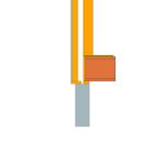
Starting from the bottom, I’ve shown an 8″ poured concrete foundation with the first floor resting on a 2×4 plate. A 2×6 load bearing wall sits atop the floor system made of 14″ tall joists and 3/4″ sheet. The exterior non load bearing 2×4 wall sits on a 2×6 plate cantilevered out 2″, effectively leaving 1.5″ of the 2×4 studs supported. Steel angle can be added to support this detail should my Engineer see it necessary. A 1″ thick strip of foam can be used between the 2×6 and 2×4 plates, caulked in place as a spacer and extra insurance against moisture from the foundation.
At the second floor I’ve shown the floor system supported by a ledger, keeping the whole system out of the insulated wall cavity. This also allows a flat plane through which the vapor retarder can pass uninterrupted (installed before the ledger). A single sheet of 3/4″ plywood joins the outer and inner walls at the plates. A double plate on the outer wall allows a slight trimming of a 10′ 2×4 to fit with minimal waste while providing a 9′ ceiling inside. A 4′ awning truss projects to provide shading to first floor windows and break up the appearance of the straight wall.
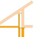
At the roof I’ve shown a raised heel truss supported by the inner 2×6 wall, a 3/4″ plywood bridge to the outer 2×4 wall, and a vertical 2×3 extension wall that allows the R80 blown in cellulose to completely cover the exterior insulated wall cavity and eliminate thermal bridging from the roof truss to the outer wall. The 3/4″ plywood bridge extends inboard slightly to allow the 7/16″ OSB attic floor to be taped securely to it. The truss overhangs 4′ to shade second story windows and, combined with an 8/12 slope, allows for a full depth raised heel to accommodate very deep attic insulation while extending high enough to keep wind washing of the insulation a non-issue (30″ as shown). An interior ledger board to support the trusses over window openings is to be discussed with my Engineer.
Not shown in these sections are the 3/4″ plywood window boxes or the 2.5″ interior service cavity to be framed with 2x3s. The service cavity will be stuffed with 3.5″ R12 fiberglass batts, compressed to give roughly R10. The service cavity allows the interior mounted ledger boards without disrupting the drywall mounting plane, as well as a space for wiring and plumbing pipe to co-exist with an uninterrupted vapor retarder. The compressed fiberglass batts will keep some pressure on the cellulose pack and vapor retarder, keeping any movement suppressed during building pressure changes.
Center of cavity wall insulation will be R54-R55 plus whatever R value I get from drywall, OSB sheething and air gaps to siding etc. I’m guessing clear wall R value should be about R50, maybe a little more.
The primary air barrier is the continuous layer of exterior OSB sheething from the foundation to the attic, bridged through the wall by the upper 3/4″ plywood bridge. The interior vapor retarder will be Intello Plus in a straight shot from the attic floor to the first floor sheething, only needing to be detailed out and around the first floor rim joist to allow sealing to the inside of the foundation wall.
Looking forward to your comments!
GBA Detail Library
A collection of one thousand construction details organized by climate and house part


Replies
Lance,
I'm not an expert so please do your own research on anything I've written below :-)
Your wall details reminds me a lot of the Rochester Passivehouse- which happens to be one of my favorites. They simplified things a bit by using a single, larger mud sill to hold both studs. Also, despite their plans- they ultimately used roof trusses with bottom chords that extended all the way out to form the overhangs. Both of these details constitute energy penalties but the house still achieved PHI certification.
Here is the link to their wall detail:
https://rochesterpassivehouse.blogspot.com/2015/12/wall-assembly-1.html
You are probably fine with having your air barrier on the exterior- especially if your load bearing wall is on the interior- but it may be worth looking into putting the sheathing on the outside of the interior wall. This will warm it up and eliminate any concerns that can exist with conventional double stud walls. You could do away with the intello too by doing this. Using intello as interior air barrier is great but requires airtight electrical boxes/ possible strapping. Adding your air barrier to the outside of the interior wall creates a service cavity- which makes things easier.
(It seems that nearly every PHIUS certified house in zone 6a and up keeps the air barrier on the inside of the wall assembly. PHIUS actually requires a separate WUFI analysis if this isn't the case. Not a big deal but something to look into. Your insulation contractor better like ladders however if you go this route.)
One final note is the OSB sheathing. There is lot written on this topic here at GBA and you are probably fine.... But I would opt for CDX plywood as it is more vapor open. Be sure to include a good rain screen gap of course. If you do use OSB then opt for a quality product like Advantech or ZIP as these have been proven to be airtight.
http://www.scrantonpassivehouse.com/musings-of-an-energy-nerd/
Good Luck!
Lance, that looks like a good approach overall. The biggest issue I see is the sheathing location; according to the IRC codes it's supposed to be in contact with the bearing studs. If allowed in your area, you could add diagonal bracing at the outside of the interior wall.
I agree with Rick about the sheathing material; I was involved with one of the "famous" failures of commodity OSB as an air barrier; a frustrating thing to discover when you do a blower door test. ZIP is better, but for double stud construction I now prefer CDX because it's more vapor-open when wet.
Thanks Rick - that Rochester house certainly does have some similarities.
With regards to keeping the air barrier and sheething structure inside the wall. I understand the concerns over wet sheething and have read many articles on the topic. Since I will have a service cavity on the inside of my vapor retarder, there will be very few penetrations to detail and very few potential leak points. With an almost complete lack of penetrations through which air can move, I have a fairly high level of confidence that moisture infiltration to the insulated cavities will be minimal. As long as I maintain vapor permeability with my exterior air barrier sheething (dry to the outside) I'm thinking I should be OK.
Yes, the airtight OSB question. I'l be weighing the pros and cons of Zip vs. OSB with a separate WRB. Zip is an attractive system but it's not cheap.
Thanks Michael.
According to my city officials diagonal bracing is allowed. We discussed metal "T" bracing. From a personal viewpoint I'm very OK with that as the outside wall will still provide sheer resistance as it is bridged to the inside wall at the 2nd floor and roof truss levels. And though not technically load bearing, the outside wall is built right up and fastened to the underside of the roof trusses at the raised heel.
Is CDX plywood considered as airtight as something like Zip? It's an option I will be looking into for sure, though it still requires a WRB.
Lance, just be careful with the T bracing, it's not allowed in all cases, but if your AHJ gave you a green light, that's great.
I have data loggers in a double stud wall with ZIP sheathing and cellulose; the interior vapor retarder is airtight drywall, and the wall definitely loads up with moisture in the spring. Diffusion moves much less moisture than air leaks, but it still moves moisture. If you're using Intello that will make a big difference.
I'm trying CDX as an airtight layer for the first time on a current project. The builder is getting close to blower door stage so we'll find out soon if it's as good as Zip. My research says it's airtight, but then again we all thought OSB was always airtight as well.
Michael, how much concern is there about the moisture content on the zip sheathing with your wall? I've been considering a rockwool double stud wall, 2x6 load bearing outer and 2x4 inner with intello between the two walls for Zone 5. From what I've been reading it seems like cdx is the safer bet for sheething as it's more vapor open, but people still will go with zip? Wondering if you can shed light on this.
Lance,
A few minor comments.
Starting at the foundation:
- For ease of anchorage, and to aid the cantilever, it might be worth considering a single bottom plate for both walls. There would be a very small energy penalty in the thermal bridge it creates.
- I joists typically need 1 1/2" bearing. You might think about cantilevering the inner sill-plate out until you have that, and can them take a comparable amount off the exterior cantilevered sill.
At the second floor.
- It may not be intended, but you show a different number of top plates on the two walls. As closely as possible you want the two walls to mirror each other to avoid differential settlement as they dry.
- The ledger supporting the I joists may be at a difficult height in relation to the wall plates. It will presumably be fastened with lags or structural screws, and it may be difficult to find good bearing in the top plates and very top of the studs.
- No rim joist is shown at the I joists (probably to allow the ledger to provide the required bearing). With no rim joist, you will probably be required to block in between each joist for lateral stability. That's pretty time consuming work.
- Below the ledger there is presumably 2x" strapping to form a service wall. That's a pretty narrow space to run electrical boxes and plumbing if you are placing a vapour barrier or smart membrane on the face of the inner-studs. Some thought needs to go into how these services will actually be routed.
- The detail shows a cantilevered roof fastened to the exterior non-loadbearing wall. Probably fine, but the wall has very little bearing-surface on the foundation.
At the roof:
- It might be a lot easier to get the truss manufacturer to include another chord over the exterior wall so you don't have to frame one.