Flat Roof Design Details
leon_g
| Posted in General Questions on
We’re having a new home designed which will have a “flat” roof. The house will be in Portland, OR, Zone 4C.
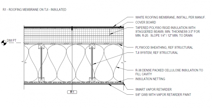
I’ve read numerous articles here about flat roof design guidelines and pitfalls, including the “ratio rule” for hybrid roof systems. I think the architects’ design (image below) checks all the boxes – R38 cellulose blown in between 12″ TJI joists, R20 min polyiso on top of deck, etc.
Also, they are specifying 1/4″ / 12″ slope, which I like because it creates a flatter roof – but would a slightly higher slope be prudent, since 1/4″ / 12″ is already the code minimum?
Any feedback would be appreciated.
GBA Detail Library
A collection of one thousand construction details organized by climate and house part
Search and download construction details


Replies
The roof you have designed should work great, I'm in a much colder climate and very rarely see such a well insulated roof on any new build.
The smart vapor retarder underneath is not really needed nor is the the vapor retarder paint on the drywall. With exterior rigid providing condensation control, two coats of latex over the drywall is all the vapor control you need.
There would be less ponding with a steeper slope, but a bit of ponding is not really an issue with any of the single ply roofs.
P.S. With continuous exterior insulation, your roof works much better than a standard roof which means you can also comply with code based on assembly U factor. This lets you use than R49 center of cavity insulation. If you don't need the 11 7/8" for spanning and can go down to 9.5" and scale the exterior rigid accordingly, you'll still comply based on U factor. Slightly thinner roof profile.
Akos, thank you for the quick feedback. You are right, this roof is very highly insulated. By my math, the rigid thickness goes from 3.5" min to 7" max over the typical 15' wide slope, leading to about R40 at the peak. Combined with the R38 of cellulose, that's an overall insulation range of R58 min to R78 max, well above the R49 requirement.
Is the roof possibly "over"insulated for the climate? We're trying to be cost conscious, and with the roof area of around 4000 sq ft, would there be significant savings by cutting the rigid thickness by about an inch? And could that savings be better applied elsewhere?
I have no idea how much an inch of polyiso costs, but it's got to be significant over 4000 sq ft.
For perspective, we're shooting for the "pretty good house" - R23 cellulose in walls, slab on grade with perimeter insulation but not under the entire slab, tilt and turn windows at around U=0.20.
Also, is there any harm in the smart vapor retarder and vapor retarder paint, other than extra cost?
In zone 4 your are probably around 4000 heating degree days. This is a ballpark, but the heat loss through the roof over the whole season (assuming ~R60 roof) is:
4000HDD*24h*4000sqft/R60=64 therms. If you are heating with electric resistance using $0.15 electricity, that cost you
64Therm * 29.3 kWh/therm * 0.15=$281 for the season.
If you use a heat pump, that would reduce that by about 3x to ~$100.
So if you reduce your assembly U value to code min (most likely R38 assembly), the cost of heating would go from $100 up to $160. So not a lot saved.
You can do the above math for any surface of the house including windows to see where your dollars are best spent. My guess an R60 roof with a lot of foam has no reasonable ROI in your climate. Than again, this could be a moot point if you need the 11 7/8 rafters for spanning, in which case you need the extra rigid to match the thickness of the fluffy insulation.
In milder climate, your best return is getting the house air tight, which should be your main priority. Make sure to figure out all your air barrier transitions (slab to walls and walls to roof) and spend money on getting those details right as well as a blower door testing to validate it.
Sometimes it is worth it to add a bit of extra cost and insulation to increase comfort, this is mostly around things like large windows or floor cantilevers.
The smart vapor retarder doesn't hurt for the ceiling but vapor barrier paint is not the best idea. The perm rating of most vapor barrier primers is pretty low and won't allow for drying to the interior which is what you want with this type of roof assembly. Using both is a bad idea. In your mild climate, the smart vapor retarder doesn't buy you much if anything, I would use that money elsewhere.
I’ve designed hundreds of flat roofs with 1/4” slope in the SW. You guys need to do some basic math. If your 3.5” of rigid foam has a 1/4" slope, every 4’ horizontal run, you’ll lose 1” thickness… If the house roof is 14’ wide, you’ll end up with ZERO insulation on the low side.
The 2021 IRC Table 806.5 tells you that you need 1.5” R10 min. polyiso (on the low side), that means you need to add 1” polyiso per very 4’ horizontal run of the house roof to the high side. So if that roof is 20’ wide, you should finish with 5.5” R36 on top of the roof decking on the high side.
Also, in between the scuppers and gutters, you need to have crickets to divert the run-off water to the scuppers or drains.
Another option is to install the TJI’s on a slope, with additional plates on the high side, but that means that you need to rip 2x to flatten the ceilings underneath, unless you like the slopped ceilings.
A third option is to use flat roof trusses with the slope and parapets built-in. Last two options are easier to install rigid foam on top of the decking.
Armando, the 3.5" thickness specified in the drawing I uploaded is the minimum thickness, and goes up from there, not down. So over a 15' roof (the longest run we have in the design), that's an additional ~4" of thickness, for an additional ~ R20 above the minimum R20. So R20 + R20 from the rigid, plus R38 inside, for a total R78. Seems like an awful lot of polyiso (?).
Going back Akos' comment about the 11-7/8" TJIs, they "may" be needed for spans, we do have some long spans (structural engineering is still in work). So that makes sense that we need R38 inside to fill the 11-7/8" space. But for the 20% roof ratio we need for Zone 4C, the rigid on top can be R10 as a starting point, instead of R20. So that's an "excessive" ~1.5" of polyiso that the architects are specifying, I'd like to reapportion that expense to something else if it's not needed.
Most of the roof has gutters all around, only one small area (a pop-up above the great room) has parapets and scuppers. The scupper downspouts (if that's the right term) appear to just dump the water on the flat roof below - does that sound OK?
"The scupper downspouts appear to just dump the water on the flat roof below"
Best to include a precast splash block below each scupper downspout. Best practice and cheap insurance.
Thank you, that's a good tip. Perhaps they have these in the design, I just don't see them, so I'll ask the architects.
Too much polyiso? Yes and no. You have twice what is required for your CZ, but it won hurt, and as long as you are not concerned of your ROI, it’s your money.
I wish I could take the "it won't hurt" route, but money is definitely a factor for this project. So I'm asking from the standpoint of whether the cost of the "excess" insulation on the roof could be better applied elsewhere - for example an outer layer of rigid on the walls to avoid thermal bridging, or under the slab.
In other words, if we are only meeting the code for walls and slab, but are far exceeding it on the roof, is that a good balance? Should we instead upgrade the wall or slab insulation a little? I understand that this whole insulation topic is a "system", it's just not clear to me how to calculate the cost/benefit for the different parts of the system.
I also noticed that there appears to be a 6" gap in insulation at the slab perimeter above grade, which seems wrong (image below). Should this be handled differently?
Leon,
That gap definitely needs to be covered, and the rigid insulation brought up to the bottom of the thickened slab. It's a bit fiddly, as you need to provide protection for it above grade, but if the foam isn't continuous you will lose an awful lot of heat through that concrete thermal bridge.
From my perspective, I would cut the polyiso on the roof to 1.5”-2” on the low side, and I would use those savings in the wall assembly outsulation and foundation insulation, as you mentioned. I also prefer to use roof trusses, since they have the pitch and parapets built in, and you don’t have to taper the polyiso, and there is a cost for that process too. It’s a lot easier system to build, IMO.
I’m including two foundation/slab insulation options I use to avoid thermal bridging, bugs and termites.
Randy Williams just posted a good blog with similar details: https://www.greenbuildingadvisor.com/article/the-value-of-modeling-software-and-mock-ups
Armando, thanks for those details. We plan to have the top of the slab serve as the finished floor, so the approach of insulation on top of slab of won't work.
Maybe the other one will work, but it'll be a significant change from what the architects have designed for the foundation. I'll certainly ask them about this.
I should probably start a new thread to discuss the house's insulation in general, since this post was meant to focus on the roof.
On roof slope, 1/4" min can be fine, but if you have crickets then the valley slope will be less. Also if there are construction tolerance issues, long term creep/sag of the structural members, etc., you will also get flatter spots. As a starting point I try and use 3/8" minimum for primary slope and 1/4" for secondary.
Daniel, good point about the crickets, I don't see them shown in the plan (image below). We should have them at the skylight locations (circled), right?
I'm trying to understand the "quarter diamond" crickets at the central pop-up roof (with the parapet), leading to the two scuppers. Looks like they have the same slope as the roof in general (1/4" / 12") - I read in a few places that cricket slope should be twice the underlying slope (?)
Typically skylights such as Velux don't require crickets. They should be at least 12" from ridges and valleys and it looks like some are too close/overlap. The quarter diamond roof crickets are too small in my opinion. The key is the angle with respect to the main roof slope. Assuming they are about 1:4 plan ratio (left:up), the valley slope is 1/4":4 feet or about 0.6% instead of 2%. Any imperfection in the roof lap can cause small ponding which leads to quicker deterioration.
For 1/4" slope roofs I prefer 1:1 crickets, for 3/8" slope then I try to use a 1:2 plan ratio for the cricket.
The backwards slope of the cricket itself can be net 1/4":foot, which means if it was tapered insulation the board would be 1/2":foot to make up for the main roof slope. That is probably what people mean by twice the underlying slope.
I also recommend making sure the scuppers are large enough to not be blocked by leaves or other debris. Your architect should calculate the min size per code based on roof area. Even if not required my preference is to have an overflow scupper at least 2" higher up on the roof in case the main gets clogged.
Daniel, thanks for the comments about the skylights and ridges/valleys, the skylights do overlap these, or are very close to them. Unfortunately they can't be easily moved as they are located over small areas (bathrooms). Is that concern also valid for membrane roofing (without a metal valley)?
Can you help me understand your comment about 1:1 crickets? Most places I read (e.g. GAF guidelines for tapered insulation) says to follow the 1/3 rule - "3:1 ratio based on a standard diamond cricket, where the width is 1/3rd the overall length."
Here is what they say about the cricket slope - "Industry standard: crickets are double the slope of the tapered system used. Doubling the slope of the cricket ensures that proper drainage occurs. Anything less than double may result in ponding issues and/or slower drainage." - so that sounds like we should go with 1/2" / 12" slope for the crickets.
And thank you for the point about having secondary scuppers, I think those are definitely a must.
Membrane roofs can be easier to detail, PVC with welded seams is most forgiving, EPDM with adhesive seams is not good for complex intersections of overlapping membranes. After looking again it seems the left S-2 skylight that overlaps a ridge instead of a valley which could work for the roofing, but seems quite awkward.
I think the slope along your cricket valleys is almost flat, ~1/2 of a percent. Increasing the plan geometry of the cricket slope to 1:1 will help, or increasing the main roof slope to be steeper than 1/4":foot. For a 1:3 cricket, if you calculate a point 12" right and 36" up, the rise is 1/4" (up the main roof slope), the length along the valley is about 38" (hypotenuse) and 0.25":38" = 0.00657 or 0.66% slope, almost flat. Yes it can work, but I prefer steeper slopes to protect against imperfect construction. Increasing the main roof slope from 1/4" to 3/8":foot will have 1% slope for 1:3 cricket valleys. Or a 1:1 cricket on 1/4" slope gets 1.5% on the valley (0.75":50"), no change to main roof slope and you just buy more tapered insulation.
Yes, for the tapered insulation, double the slope of main roof will net a proper cricket back roof slope. Sometimes crickets are made in the field by tapered framing on top of sloped roof framing, so I generally only refer to the true roof slope of the cricket.
Leon,
If the budget is tight, the best place to reduce cost is to simplify the design.
Looking at the roof plan, I can tell you that won't be simple or inexpensive to build. Little design details can easily add a lot, for example your popup, besides needing walls/parapets/scuppers, it also needs a lot of structural material underneath to support it. If you can raise the whole roof up to the same height, maybe add a bit more slope to reduce the eaves height, it will simplify a lot of things. Very few people will complains about having extra tall ceilings in a bedroom.
Transitions like that are also a challenge for insulation and air barrier continuity. They also create a lot of additional potential leak spots down the road.
I can see wanting something more than a simple monopoly house or borg cube shape for a home. All those design "details" can have a long tail end that can add to a fair bit of cost.
Your architect will never say no to any design detail you ask for and your builder will gladly build them. It just all comes at a cost.
Akos,
Thanks, you are definitely right, this popup feature is a hit to both cost and simplicity of the design. We originally started the design process with a 'dream home" in mind, and quickly came back down to earth after seeing the cost estimates :).
Our budget is far from small, but as our architects told us, still not big enough to have (m)any "wow" factors. So this popup over the great room, with its 14 ft ceiling, is the only "wow" factor we have left. We knowingly (or perhaps ignorantly, the jury is still out) decided to keep it in the design.
That may change when we get the structural design finalized by the engineer - if it starts looking like a skyscraper structure, we may rethink.
The roof deck itself is flat everywhere, so that should not be complicated. All the slopes are achieved with tapered polyiso - I'm hoping that is not too hard to do?
This just rubs me the wrong way, "our architects told us, still not big enough to have (m)any "wow" factors".
I hardly ever criticize other professionals for their work, as we all have a different take on the same project, but this Architect is wrong by making such a statement.
Architects with that attitude give the design community more ammunition to blame for bad work. Any good Architect or Designer should be able to give his/her clients a WOW factor, regardless of budget or whether the project is an affordable housing or a palace.
I just wonder about his/her imagination, knowledge and construction experience in high-performing homes.
I agree, even though they may be right from the purely practical standpoint. But it sure took a lot of wind out of our sails, we thought that at $400-500/sq ft, we could have a bit of "wow". Apparently not in this day and age.
I would think, generally speaking, you have a generous budget, but it’s common to spend $200 per sqft just as easy as $1500 sqft, depending on your selections and many other factors.
Price per sqft is a bad rule to follow, especially in custom homes. Builders and Realtors use it every day, as if anyone can tell you what the price of cars or the price of a grocery bag, without knowing what’s in it. IMHO, I think is misleading metric commonly use that can be prejudicial.
The price of land and land development can vary a lot. We’re building a $1.5M house on a $125k lot, and I’m finishing plans on a house that the lot cost is $1.8M. Several years ago, I designed a house in CA in a double lot, with a price of $11M.
Any Builder in CA and FL coasts or areas of NYC and Seattle know that building a house there can be several times over what most of the country experiences.
We also don’t know the costs of materials and labor in your area. Usually, down here in the south (in TX), we get anywhere from 30%-60% immigrant labor, depending on the trades, which is cheaper than other parts of the country.
Malcolm, looks like I can't reply directly to your earlier post: "That gap definitely needs to be covered, and the rigid insulation brought up to the bottom of the thickened slab. It's a bit fiddly, as you need to provide protection for it above grade, but if the foam isn't continuous you will lose an awful lot of heat through that concrete thermal bridge."
I've been thinking about this, and reading all the GBA articles on slab edge insulation, like this one - https://www.greenbuildingadvisor.com/article/getting-slab-edge-insulation-right. While I definitely see the value of insulating that edge, it seems (especially in the comments) that there is no reliable/easy way to protect this setup from termites, and some folks say that taking the thermal loss hit is the lesser of two evils compared to the risk of termites.
Is there a generally accepted method for protecting against termites when using slab edge insulation, or is that still a valid concern?
Leon,
I don't like designing things so you have to make fundamental compromises between aims.
Slabs with integral footings seem to be a detail that causes a lot of those types of choices. Not only in how to maintain a continuous layer of insulation while staying safe from insect degradation (something the is a lot more important when the insulation is placed under structural footings that it usually is), but also the conflicting aims of getting deep enough footings while maintaining a joint with the slab - which often leads to the odd shape you have ended up with, using a lot of concrete but having a very small bearing area.
For those and other reasons I use separate stem-walls instead, which get insulated on the inside.
Malcolm, I agree, but my understanding is that the stemwall foundation is significantly more costly than the monolithic one that is in our design. I'll talk to the architects about the slab perimeter insulation and let you know what they say.
Re. termites and exterior slab insulation. One approach is a sheet metal termite sandwiched between 2 layers of sill gasket material. This goes on the slab and the sill plate of the wall on top of that. The wall sheathing also does not extend down the face of the foundation at all, as the termite shield is in the way. The shield extends out beyond the outer face of the exterior foundation insulation, sloping to shed water.
Here' another detail that looks odd. This is the roof over the ~10'x10' area connecting the main house to the ADU.
Looks like the roof slopes from one parapet towards another parapet, and the water is then channeled towards a downspout at one end (I don't see a secondary slope towards the downspout).
The first image shows the higher part and its parapet, and there appears to be a gap between the upper cap and the parapet flashing. And if I read the second image correctly, there is nothing covering the framing of the parapet, it appears to be exposed to the outside.
Maybe these are just CAD errors because these are not the finished drawings.
Detail 5 clearly has drafting errors, components got moved, sometimes that just happens. Can't tell you how number times I've done a check plot, looks good, then later looking at drawings I see obvious oops.
The detail on right looks incomplete plus a little drafting error.
With those errors and without seeing other referenced details it would be premature to critique the details. Besides Armando's comments I wonder why the detail on the right has a note for both cedar and flashing under the eave / soffit.
I recommend you meet with your architect and ask them to walk you through their details, starting with roof plan, building sections, then details, etc. Doing this in person or on zoom with shared screen should answer many of your questions and/or have the architect realize issues they need to address.
Daniel, you said "Increasing the main roof slope from 1/4" to 3/8":foot will have 1% slope for 1:3 cricket valleys. Or a 1:1 cricket on 1/4" slope gets 1.5% on the valley (0.75":50"), no change to main roof slope and you just buy more tapered insulation."
I understand the math now , and your post makes sense. So the 1:1 slope looks like the right answer, I'll discuss with this the architects (along with all the other questions I have about the details on the drawings).
To be fair, they gave us the "80% completed" drawings, so that may explain why some of the details are either confusing or in error. I will ask them for a discussion on the topics of insulation strategy, air barrier strategy, and roof drainage/sealing strategy. I think that many of these items can be finalized later, even after construction start, but at the same time, it seems like it's best to try to submit the best plan possible for permitting.
But I agree with you, and will ask them to walk me through their thoughts on all these important items.
[they gave us the "80% completed" drawings] - a lot gets done in the last 20%!
No doubt! It makes it hard to review the documents though, because we don't which items they'll find and fix on their own, so we're erring on the side of pointing out all things that look wrong.
I my 35+ year experience, I've learned that details on drawings are for the benefit of who is actually building the house (framers, roofers, etc.), so they know how things are put together, and they must be as clear as possible. Failure to do that, you can create future problems. Details are definitely not for the Banker, the ACC at the HOA, or the owner.
I find both of your details confusing, mostly because they show few or no labels, and w/o a wall section, it’s not clear the context which you show them.
Having said that, on the first detail, the fascia is under the parapet flashing, and on the second the fascia is outside of the flashing, and wall covering should be detailed on both sides.
I do not understand what the first detail “space” is for, I’ve never seen it drawn that way, not that it’s wrong, it’s not clear. Also, it has exposed plywood.
Usually, the top of parapet wall is on a slope (copings), for obvious reasons. One detail shows the cant strip, the other doesn’t, etc., etc.
Agreed, I think there are some errors in the drawing, so I will ask the architects to explain their strategy.
Armando, regarding costs, our market in Portland appears to be nuts, so the high costs are not unexpected. On top of the cost of land, we'll probably be spending about $1.5M - 2M on the 3500 sq ft house. We were hoping that would get us some cool features, but we definitely had to bring our expectations down over the last year of design work.
Reviving this thread since we got a couple of responses from the architects on my questions.
Regarding the request to reduce the rigid insulation from R20 to R10 minimum (which would still meet the R49 requirement given the R39 cellulose under the roof deck), they pointed me to R806.5 (picture attached), which does seem to require at least R20 rigid (6.2). Am I interpreting it correctly?
They also replied to my question about secondary scuppers, which seemed to be required by 903.4.1 (attached) by saying that " Our interpretation is that a scupper or overflow drain is required as a back up to a primary roof drain. I don’t interpret that a scupper is required where the primary drainage is already a scupper.". Would you agree? I'm not sure I agree with the scupper vs drain distinction.
If code says you need R20, you have to install R20 even if it is not needed. Strange, you don't need that much exterior rigid in Zone 4:
https://www.buildingscience.com/documents/building-science-insights-newsletters/bsi-100-hybrid-assemblies
See if you can at least get away with an average of R20 including the tapered part. There is no energy saved by adding more insulation in this case.
They are correct the code does not require a second scupper for this condition. I like to have them as a backup if there is danger of the main scupper getting clogged by leaves. If you do yearly roof inspection this shouldn't be a problem. (Or if there are no tall trees nearby.) You can also consider the other side of the flat roof as overflow, assuming the framing could support the weight of water filling up one side.
I asked them to add the secondary scuppers, seems like very cheap insurance.
They're still pushing for TPO, but from what I read PVC is better (though more expensive)?
I'm not an expert, my experience with PVC is all commercial. For your project either should be fine, more important is which system has better range of competent roofing contractors in your area. Such a small area of flat roof will be pricier and you may have trouble finding one roofing contractor to do both systems (flat & sloped roofs).
I realize I never posted the roof plan, but the entire roof of the house is "flat", not just the pop-up.
It's funny, the architects recommended TPO precisely because according to them "it is easier to find a roofer in the Portland area familiar with TPO", but our builder is recommending PVC.
I’ll answer the first question. Per IRC TABLE N1101.7(R301.1), all three counties where Portland is located are in CZ4C. The 2015, 2018 and 2021 IRC R806.5, don’t have R806.5.6.2. I’m thinking that you may have a local amendment to that section, if that’s the case, you shall.
I’ve attached a PDF copy.
They're using the Oregon Residential Specialty Code, which differs from IRC. I'm attaching the relevant version of R806.5. It does seem to call out R20 as a minimum. My understanding is that it is not as much for energy savings as for condensation control.
There is another section on alternative methods for using the average U value, which is what Akos is referring to. But I think that while it allows you to have less than R49 in some areas of the roof if you have more than R49 in others, I don't think it trumps the min R20 requirement specified for condensation.
So unless you guys think I'm totally misreading something, I think I'm going to have to drop this, I have too many other battles to fight on this project.
As Armondo said, "you shall". So R20 it is. Sometimes there are provisions for accepting an engineer's drawing but that might not be worth the cost.
As for the scuppers, since you need some overhangs, I think the simpler design to skip the parapets. Go for a simple mono slope with overhangs for shading and use standard eavestrough.
Agreed, R20 it is.
As for the pop-up design, we're at such a late stage that I don't want to redesign the parapets to overhangs, it'll require redoing the structural design (which, as you predicted, is complex in that area, with a number of steel beams). I agree that lack of shading may be a downside, but I think the architects (and more importantly, my wife) like the idea of having clear sky view through those clerestory windows. Happy wife happy life :).
I have some updates on the roof design, the architects changed the cricket slope to 1/2" / 12". The cricket ratios are about 1:2 in some areas, and about 1:1 in others (picture attached). So hopefully this will be an improvement.
They added overflow scuppers, though I don't think we need scuppers and downspouts for the overflow ones - just openings in the parapet about 2" above the primary scupper.
We also removed the two skylights that were near valleys.
And since we had an offshoot discussion on slab insulation, I'll share the new design - the builder said they'd prefer to do the foundation in two pours, one for the stem walls, followed later by the slab, after all the plumbing has been located. He said the cost should be comparable. This gives us the ability to address the lack of slab edge insulation in the original monolithic design, and the structural engineer proposed a 5" wide stem wall that would allow us to "hide" some tapered insulation under the exterior wall, as shown in the attached.
What do you guys think of this?