Retrofitting an HRV
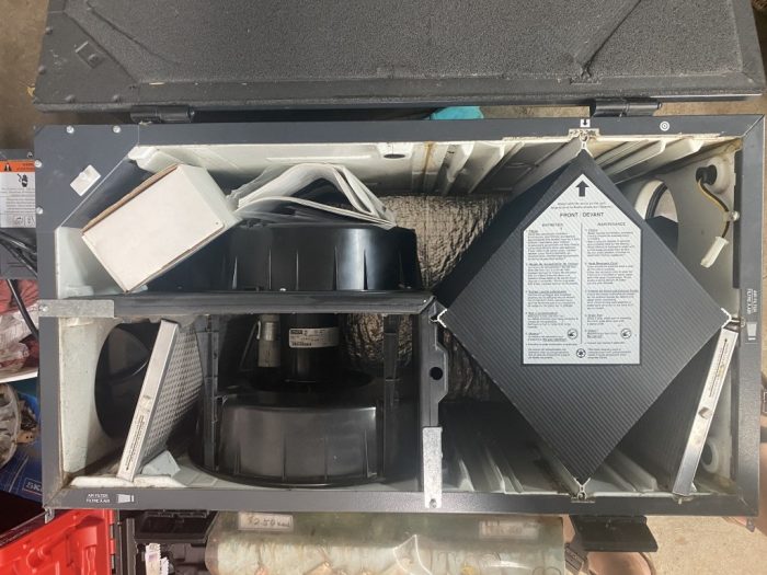
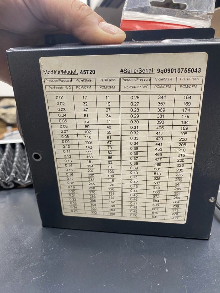
I’m conducting a bit of a science experiment. Can you take an older HRV, (in this case with a known fire hazard motor), and retrofit it as an ECM miser? Model is a Venmar AVS Solo 2…apparently was quite a popular unit. The unit was slated for disposal. In the initial test (temp probes at all four ports) the HRV is “bench” balanced via a vane anemometer to 88 CFM, using 19 watts total power, with a measured efficiency of 89% over about four hours of testing with outside temps 37-40F. I’m using two EC fans, mounted externally. The questions are about balancing: 1. There is a balancing chart attached, however my assumption is that it would be useless in the current configuration with the OEM motor and housings removed. 2. If I take measurements of static pressure on the door ports in the new configuration (with measured CFM on 5′ long, 6″ ducts), can I correlate these to balance once fully installed? My thinking is to take statics via the door balance ports at all the motor speeds, measure flow and basically make a new chart. 3. Once the system is fully installed, will the chart I made in step 2 be ok to determine CFM rates? 4. I am not balancing using dampers, but rather EC fan speeds as there are two separate controllers. I’m hoping some of you trade gurus out there will chime in on this one 🙂
GBA Detail Library
A collection of one thousand construction details organized by climate and house part


Replies
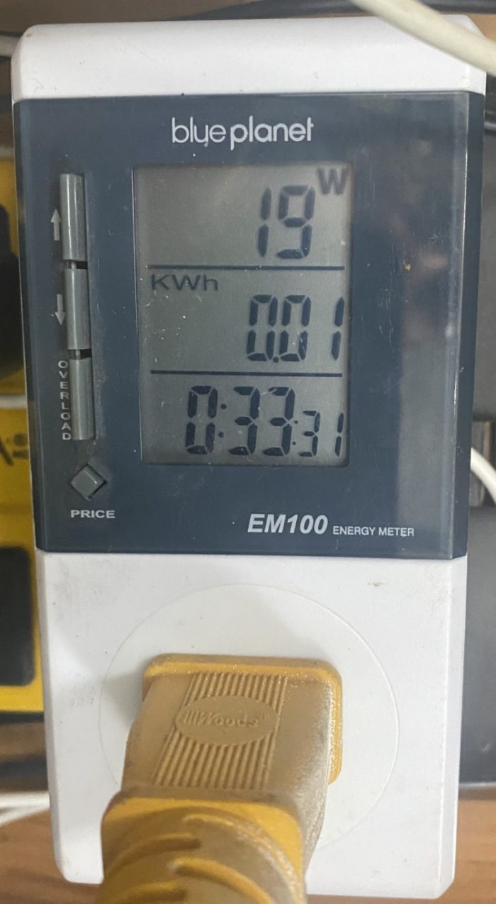
Sorry, could only attach 5 files. The appliance label, CFM calc from the vane anemometer and performance. I ran my test (heating intake air to about 70F) for about four hours. Sound was measured 1 meter from the motors at 54.5 db. Surprisingly quiet with no silencers (coming later) installed.
I was able to spin up the OEM motor (just barely) and tested power use at 300 watts. The motor lower sleeve bearing (poor design that starts fires!) had enough play to allow contact between stator and rotor...so my guess is that a new one would use less power. Still, from the OEM psc motor's rated 210 watts or so, we're down to just 19 watts (including the HRV control, and two motors running).
There is a recall in effect for these, and similar units: https://globalnews.ca/news/6298646/air-exchanger-recall-canada/
You can buy a new motor, but it's $200, and uses the same (bad) sleeve bearing design. The "safety" device they send out is a plug with an embedded 3 amp fuse. It does not fix the motor issue, but will prevent a fire.
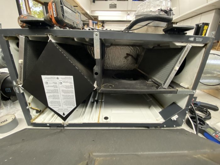
Check where the pressure ports are on the unit. These are typically right across the core before the blowers so changing the blowers won't effect pressure readings. I've run into issues is when changing out the filter on the core to something more restrictive, had snake in a pressure tap right between the filter and core to get proper readings.
Akos, 3 ports do surround the core, except for this one. I don’t understand why it is located in the “insulated” hollow divider between stale/fresh. It’s referencing the house’s inside static pressure?
The other surprise is how efficient the unit is. It's well above what I was expecting. I'm approaching the test conditions for these units (37F outside) yet efficiency measures between 89 and 92 %. I am assuming this is because I'm reducing flow over the core from a design 180 CFM, to 80 CFM ?? I'm taking temps every 120 seconds using 4 x DS18B20 probes on all four ports.
The difference is substantial when say comparing to the existing Panasonic FV-04VE1 which at this moment is pulling in 30 CFM with a return temp of around 37F. It's about 27F ambient, and would be considered a warm winter day here. That's 28 800 BTU per day, so running our furnace for a full 30 minutes to bring that air to temp.
If the retrofit HRV was in place right now, I'm figuring about 11 500 BTU to bring that 88 CFM to temps. Triple the air flow with 1/3 the cost, while using slightly less power (19 watts vs 23 watts).
Ignore the balancing question..I figured it out.
I've got the HRV "retrofit" working in place...just a lot of clean up to do. I've learned a great deal doing this project, but the biggest indication that it's working well is the CO2 PPM readings. The attached image shows CO2 levels in this 100 year old house with no ventilation running at all (the small Panasonic spot ERV was removed two days ago). CO2 reached a peak of 1700 PPM yesterday morning...and winds were about 20km/h.
Can you guess what was going on here? Not sure if unbalancing an HRV is a good thing to do at -30 C, but it sure makes for some interesting numbers. 95% percent efficiency from an old HRV...cough, cough.
I've already integrated the EC motors (via Leviton 0-10V dimmers for speed controls) to the kitchen exhaust fan system . This works better than expected to sync the home's ventilation rate with kitchen exhaust hood use.
Just a quick update here, more as a PSA for anyone looking to take the same route.
Moving fans outboard of an HRV does change the pressure drop around on the cores. This had some puzzling consequences (as in water accumulating in the case, and freezing) which I finally sorted out once I carefully observed water drainage and then measured the relative air pressures around the core (at the four airstreams). I'm pretty sure there is near zero interest in why, (ha) but I have attached an image to explain what was going on.
I've resolved it by stopped the fans after the defrost cycle for 60 seconds. This allows air pressures in the HRV unit on all sides of the core to equalise, and voila, water drains like it should. Using an ERV core would be far simpler as these issues go away.
This project has really highlighted the energy "penalty" during defrost at cold temps. I understand too why the NRC has suggested that preheating HRV/ERV air may actually use less energy than just using the the factory defrost cycles.
During -15 C (5 F) nights, the unit needs to run a total of 20 minutes in recirc mode, in my case at 90 CFM. During this 20 minutes, the air leaving the ERV is at 58-64 F for most of that cycle, so lets assume an average of 62 F, which we need to warm up to 72 F. That would work out to about 24 000 BTU (7000 watts) in a day, or running our 60 K BTU furnace for about 25 minutes to provide that heat. Again, this is energy required only to defrost the unit...we're not including the energy to warm the incoming ventilation air. The unit efficiency when running at 5 F (-15 C) averages in the 80% range, so not the 90% I was getting during bench testing.
Dennis,
This is all great information, have used the Venmar many times over the years. The design weakness was an inadequate lower sleeve bearing, were you able to improve this in your retrofit?
Yes, but it's not what you're thinking :-) What I've done is not commercially viable (unless you are crazy..ha), but it is a route for a homeowner wanting to take things up a notch and learn a few things. It's 100% a viable way to take an old/inefficient system and increase efficiency a great deal.
The replacement PSC motors are the same (270 watts in this case) with a problematic sleeve bearing that wears prematurely and can cause overheating..and a fire. Venmar will send out a plugin 3 amp fuse as part of the safety recall, but they have not resolved the motor issue.
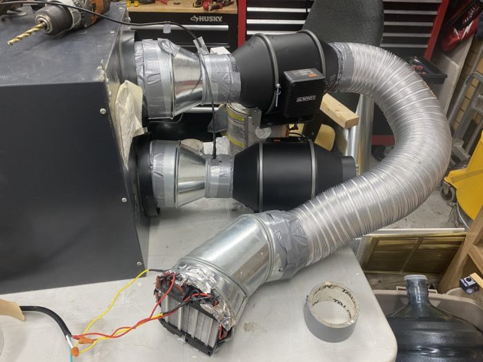
I have removed the OEM internal motor and fan assembly entirely, replacing with external inline EC fans. The system specs (using the two ECM fan motors) out at 26 watts total power required at a measured 50 CFM, and 70 watts or so at a measured 90 CFM. This is a mess still as I'm not 100% done with testing, but you'll get the idea via the attached pics.
The system is integrated and controlled by a Hubitat automation hub, although it can still be be managed with the OEM controls, and a few added Levition 0-10V dimmer wall switches for motor speed control. This allows me to do some make up air function when the kitchen hood is running, running the high efficiency fireplace etc. We've taken an old and "dumb" ventilation system and made it very smart :-)
You have taken Reduce, Reuse and Recycle to the next level, great work. Does the lower sleeve bearing failure and the somewhat unusual environment in the HRV seem connected? I am amazed at how long some sealed bearings go, in a typical electric motor for instance.
I did have a look at the OEM motor, which was worn to the point that the rotor and stator were in contact (hence the fire risk). The lower bearing was quite shot, but it is not a ball bearing or sealed in any way. It's just a basic sleeve bearing. In the OEM setup, the motor is on the cold side of the exchanger, perhaps to aid in cooling. It was the lower bearing, not the upper that was excessively worn, likely as it also bears the weight of the assembly.
In my setup, the two EC motors do not see temps below freezing as both are on the warm side of the core, and they use ball bearings. Hopefully they will last longer :-)
Given this project, I'm wondering if a business opportunity exists for a modular system where the core, motors etc. are not all in one housing? Zehnder I believe monitors the four air streams and uses this information to manage the unit.... I understand a lot better now why you would do that.
Things are cleaned up and I've added a few PTC inline heaters to temper the incoming air. I'm using Zooz Zen72 dimmers (rated to 600 watts resistive) to modulate the heaters depending on supply air temps via the automation system.
Temps have dipped as low as -20 F with no issues so far :-) The PTC heaters, EC fans and HRV dampers are controlled completely by automation, but the status LEDs provide a quick visual of what's going on with the system without pulling out a phone or computer. The third attachment is a view of the Hubitat dashboard as the system is in a defrost cycle.
I've setup a few "CFM profiles" at 55, 60, 75 and 90 CFM which ramp the EC fans for balanced air flow at each set point. The system also responds to the kitchen exhaust fan which will set the system to the 90 CFM level if the induction cook top is in use. 55 CFM continuous is keeping the 1800 sq/ft space (four humans, two cats, one chameleon, ha) at 600-800 PPM Co2. I'll be adding control via a C02 sensor which has not arrived yet so the system will be held off if we're away, ramped if we have company over, etc.
It's been an interesting project.
Final updates. It seems like the initial concept of minimising resource use to "intelligently" get to the end goal (clean, fresh air) has very much come to fruition on this project. It's pretty surprising actually how one can push building science a bit with off the shelf EC fans, automation bits and sensors.
I've learned quite a bit going along, particularly with managing the automation bits. I had about 10-12 rules previously which managed everything (clunky), now down to 4. The system will be a lot more efficient now with the current setup:
1. The HRV defrost cycle fires up twice an hour if temps are below freezing, but the time it spends recirculating (defrosting) is dynamic. In a defrost cycle, the code just checks every 30 seconds to see if the core has warmed up to 59 F, then resumes normal ventilation. Getting a simple conditional loop (just one line of code) with a repeat was key here..super simple once I figured it out. The OEM printed circuit board is programmed for for three defrost cycle time, given a temperature window determined by one thermistor. By tightening this up based on actual temp measurements, the system will spend more time in ventilation mode if required.
2. The CFM rate (amount of air flowing through the system) is controlled by live Co2 sensing. Again, pretty simple with the Ecowitt WH45 air quality sensor attached to the system. This system integrates nicely with Hubitat, sending live data every 2 minutes.
3. Wattage to the post HRV heaters is continually changed based on current air flow, current air temp, and target temp so that the air entering the main living area is 65 F or so. If the HRV is running at 50 CFM, and air is coming in at 58 F (cuz it's 8 F outside!) then we can figure out how many btu/watts are required to heat that air. The formula for BTUs required is 50 CFM x 1.08 x Temp delta. So if we want 50 CFM of air to be 68 F hitting the room, we need to add 50 x 1.08 x (68-58) or 540 BTU. Divide that by 3.14 and we get 171 watts of heat.
Turns out that outputting 171 watts of heat to my inline PTC heaters does indeed raise the temp from 58 to 68 F. Increase the CFM, or lower the input temp and more watts are needed. I scratched my head a bit on how to turn this information into a few automation rules that would set the Zooz dimmers connected to the heaters based on live data.
The dimmers use a setting from 0-100 so I needed to figure out how many watts the heaters used at each dimmer setting. I took about 10 measurements using a kilawatt type meter. Then I plotted those points to find that the dimmer/vs watts relationship was pretty linear.
Slope Calculator
This slope calculator solves for parameters involving slope and the equation of a line. It takes inputs of two known points, or one known point and the slope.
https://www.calculator.net/slope-calculator.html?type=1&x11=115&y11=30&x12=320&y12=55&x=53&y=12
The equation from that little math lesson provides me with a way to calculate a dimmer setting (0-100) to get to a given wattage at the heaters:
DIMMER SETTING = 0.122 * WATTS + 16
So combining the formula for watts and the dimmer, now I had a formula that would tell me what dimmer setting to use for a target air temperature. The /2 in there is because I have two heaters so each will get half of the total wattage requirement fed to them. The wattage to the heaters is therefore tweaked every time CFM, or HRV fresh air delivery temp changes (which in practice is every 1-2 minutes).
DIMMER SETTING = .122 * (((CFM x 1.08 x (Temp Delta))/3.41)/2) + 16
The air quality stats over 8 hours demonstrate that all is working as it should :-)
Great work, Dennis
Too often we fail to recognize innovation, I applaud the work and the reporting. Early on when HRV's were first used, controls were just not available. Then came timed on/off with humidity and remote boost, quite an improvement.
Thank you :-) I figure there are very few folks who will care about this work, but I knew I'd find a few here!
There is a lot of low hanging fruit in our search for sustainability. Building energy consumption for us in North America is a big one.