Mounting an Inline Intake Filter Box
I know this question has come up a couple of times recently and there are some old threads still with activity, but I wondered if anyone who had built an externally-mounted ERV intake filter box had plans/sketches or photos they could share?
I’m considering building a housing to mount an inline filter box like this one (https://www.hvacquick.com/products/residential/Filter-Boxes/Inline-Filter-Boxes/HVACQuick-CFB-Series-MERV-13-Inline-Filter-Boxes) soon, and am curious about how to best frame out the box and how (or if) I should handle flashing details at the intersection of the filter box roof with the existing siding?
GBA Detail Library
A collection of one thousand construction details organized by climate and house part




Replies
Working on one now using a 16x25x4 pre filter and 24” carbon canister filter. A diverter damper allows the carbon to be included/excluded as required..I’ll post up a few pics when it is done.
It’s under an eave, so flashing is not an issue. The box is supported by a French cleat lagged to the brick, which allows you to space out from the house. If you do this, then you can just flash the cleat like a window opening and slope the filter box cover away for drainage.
It’s in pieces in the shop but the external bits are all done. I’ve also sorted a housing for the stale air return that holds a 16x25x1 filter so I can pull the restrictive exchanger filters on both supply and return. This should save a few watts on the ECM motors.
I’m using MDO plywood with a metal roof and vinyl siding ..no point in using a purchased housing for this as none exist that will manage both the 16x25x4 pre filter and carbon canister in the same box. Pics are during construction looking from the bottom. The 16x25x4 pre filter is in a removable section (magnetically held in place) to allow easy access to change the carbon canister. The filter is held in place (upside down) with a metal frame and wire screen (not pictured) to keep critters out. The filtered air exits the chamber with two 8” holes in it. There are two holes there so that one can be opened to bypass the carbon canister when fire smoke etc is not an issue. The box is about 24”x36”x22”
The exit hole to HRV is not cut yet. It will be marked and cut out so it will match exactly with the HRV fresh air intake via a 6” 90 degree duct elbow.
That looks great!
I'm happy to see you post more about this. I'd been looking forward to more details since seeing you mention it on another thread. I've already ordered an insulated filter box for the fresh air supply which should work fine since my space is accessible enough, but it makes sense to have an exterior version that provides better filter options, doesn't need to be insulated, and could potentially be more accessible but if large enough may also need to be accessed less often.
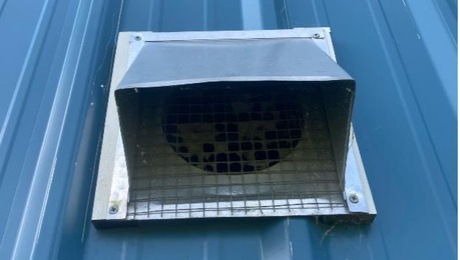
Frost buildup on cold climate (9300 hdd) HRV intakes was a problem for us in the middle of winter. The intake would completely cover with frost and not allow fresh air in. Did not happen all the time but when conditions were right, trees covered in frost, those type days. The intakes were the typical slanted metal hood with 1/4" hardware cloth.
Doug
Doug, I’ve seen that happen to the exhaust at -35C, but never on the intake. That said, the box is on the South exposure so should be fine. Winter humidity here is quite low..but I will monitor for this The automation system keeps track of real-time efficiency during operation so it is very easy to diagnose any kind of flow issue on any of the air streams.
My thinking on this is that many roof top units exist here, pulling air in via filter arrays that are outside, shielded from rain only…and none of them have external frost mitigation that I’m aware of.
Dennis,
I applaud the innovation, we need something more discerning than 1/4" hardware cloth to filter the air in our homes.
Doug
Doug, it seems that the external box is a solution for a few topics that come up here a lot with respect to the cost of ERV filters, filtration effectiveness, and static resistance. The charcoal canister has about 15lbs of carbon, as well as a large surface area. so at 100 CFM is still less restrictive than the small HRV built in filter. I've found that during smoke events the carbon setup used with the pre-filtration allows us to run the ventilation system running while keeping VOC, PM2.5 inside the home manageable.
I suffer the exact same problem currently. 4-inch metal duct for my HRV intake. I cut out the 1/4" hardware cloth at one point to stick a vac hose in there and suck out all the hoar frost. Then covered it with an unsightly plastic cage.
I have the opportunity right now to rectify this. Any advice would be appreciated. Physically can't move it to the south wall, but that wouldn't help much anyways in my situation. I do think I might be getting some moist air short circuiting with the HRV and Bathroom fan vents on the same wall as the HRV currently.
I was thinking of moving the HRV intake to the east wall below the eve and plumbing with 4inch PVC.
Doug, ( @user-723121 ) you had me intrigued with that frost comment on intake. I wonder how much of that is due to the Joule–Thomson effect? This occurs as air cooling resulting from the acceleration/pressure change of air entering the duct, pretty much as you'd see with refrigerant exiting an expansion valve. It would only occur in particular conditions, likely that we don't see here all that often, but it sure would explain why a mesh on the intake might build frost. If an object in the air stream (mesh) is cooled by the JT effect, right around freezing temps, it would explain why the mesh might be colder than the air, drop the dewpoint at the boundary, and cause freezing. In that case, a large filter, relatively low flow and therefore low velocity "should" help reduce this. In my case we're flowing a max of 110 CFM over a filter with a very large surface area given the 16x25 size, and 4" worth of pleats, which should help ameliorate the JT effect. In any case, thanks for bringing this up as it will for sure be a thing at temps just around freezing.
Freezing at very low temps on the exhaust is dealt with by the automation controller here by running in exhaust only mode (no intake air) for about 10 minutes each day (if outside temps are below -10C) at our solar peak time on the south exposure around 2pm...it melts anything that is formed on the exhaust hood. Frost on the intake side though would be harder to deal with as the ECM fans I'm using don't reverse!
If freezing actually became an issue even with such a large filter it might work to have plumbing style heat strips on the protective grill of the prefilter. If the grill is metal it could transmit enough heat across the grill to just have them on part of it in order to not impede airflow. You could have a program set to turn them on if the intake cfm drops below a certain amount and/or temperature is at a certain level.
Eli
Dennis,
I was thinking along the same lines earlier today. A larger surface area intake would change the dynamics, did not know there was a name for the frosting phenomenon. Keep up the good work.
Doug
@tim_st , if you're just looking for a filter (no carbon bits) then this might give you a few ideas. The box needs some sanding and paint still as it will be inside the house, in a basement stairwell ceiling.
This filter setup is being used for the main HRV return in the house, but could work outside as well if protected from rain and snow. The filter in the photos is a 16x25x1. The filter frame listed at $58, so not too expensive. Build quality is quite good:
https://hvacpremium.com/products/16in-x-25-steel-return-air-filter-grille-for-1in-filter-removable-face-door-hvac-duct-cover-flat-stamped-face-white-outer-dimensions-185w-x-275h
The attached pics are self explanatory but you'd need a box with a 6" duct outlet to match your ERV/HRV intake.
As I read the various posts about your HRV setup I'm curious how/where you have it ducted. I've thought about a similar filter return but wasn't sure how well it would work if the return was in a bathroom, particularly if right above a shower, but I like the idea of having the filter be accessible from the main living space.
@acrobat, my setup is a bit unconventional in that it was retrofitted in an updated 1905 home, but with severe space constraints in the mechanical room. HRV ducting is not connected at all to the existing forced air setup. There is one fresh air supply into the main living area on the main floor and one return in a basement stairwell. This works very well, aside from night time. In that case the ECM furnace fan runs at 350 CFM to push fresh air into the 2nd floor bedrooms.
Doing a new design from scratch I would have external filtration for both supply and return inline in the mechanical room and remove internal ERV/HRV filters.
Pulling the HRV internal stale air filter (approx 9x14) and replacing with an external 16x25x1 (Filtrete MPR 1000/MERV11) and filter box increased air flow from the previous balanced value of 110 CFM to 142 CFM. In other words, with the stale fan running at the same power level, we picked up 32 CFM by switching the small filter for the larger one. The increase is less at lower CFMs, measuring about 10 CFM increase when the unit is running at the lowest current flow profile at 50 CFM. This makes sense given a typical fan's resistance/flow curve. Once I finish the exterior filtration box (with a 16x25x4 MPR1000) and re-balance the system for the 50,60,75,90,100 and 110 CFM profiles I should be able to reduce power use by the fans by up to 30%. That is significant considering the unit is running pretty much 24/7.
Pic one is the filter/box assembly in a basement stairwell ceiling and pic 2 is the HRV filter (now removed) compared to a 16x25x1 standard furnace filter.
Love how it's coming together. It's encouraging to know it generally works well even with one main supply/stale exhaust point. I'm gathering parts for connecting two bathrooms to an inline filter for stale air, and should be getting my fresh air filter box in the mail next week at which point I can start assembling everything.
-Eli
Eli, sounds like an excellent setup :-)
Here’s the external box mounted up with the filter in place. The filter is a standard Filtrete 16x25x4” MPR1000. I’ll take a few more pics of the internals once the carbon filter is in place inside the filter box. Right now, as there is a MERV13 ahead of the HRV (warm side, interior)) the pressure drop removing the internal HRV filter was not enough to rebalance the unit.
Haven't gotten around to actually building a custom one yet, but did find a jury-rigged solution that has been working decently and might work for others with a similar style of intake vent who haven't have the time to build a custom box. Goal here is not to keep wildfire smoke out, but to reduce the amount of particulates that come into the sytem upstream, particularly to decrease mold risk on the intake ductwork and the ERV core.
Our current air intake vent (from the original installers of the ERV) looks like this - https://www.famcomfg.com/product/hooded-wall-vent-screen-damper-spring-gasket-hd-powder-coat-black-6-inch/
It turns out that if you pop out the internal damper there's enough space in there for an 8x8x2" MERV 13 filter to fit pretty perfectly -- I cut 1/2" backer rod down the middle with scissors and then hot glued it around all 4 sides of the filter to create a makeshift gasket, then shoved the whole filter in there. Airflow is decent (although definitely less than without the filter) and it seems to have reduced the amount of PM2.5 coming into the house.
Tim, I did a few experiments with a hood that fit over the intake, with a few of the carbon filters that you'd purchase for a kitchen fan with the re-circulation setup. It made a difference on wild fire smoke, but not much I'm afraid. Hence this setup which is a bit over the top perhaps for some, but it does address the issue of ventilation during wild fire smoke quite nicely. I will experiment a bit removing the "warm side" interior 14x14x4" MERV 13 and just going up to a MERV16, like the X6672 Lennox 16x25x5 Merv 16 Filter, for smoke events on the external box. The warm side 14x14x4 MERV13 adds about .3" w.g. static resistance at 100 CFM.
In any case, we'll call this project done, at least for now :-) The attached pics pretty much summarise the box construction. I used cup magnets, recessed into place with a cabinet door jig, to hold both the filter box itself (as well as some foam weatherstrip) and the filter in place. This ameliorates air leakage around the filter bits.
This is a mostly hidden south corner of the house so between the location, hedges in summer and the trees out front, no one will even notice the box is there.
Is there any sort of a damper on the duct connected to the Terra Bloom? Or are you assuming that when you open the damper that is not connected to the Terra Bloom, all of the air will simply get sucked through the lower-resistance open damper path rather than through the Terra Bloom?
@pnw_guy , good question. Yes there is a damper on the carbon canister, although the plan is just to leave that one open. I'm using these 8" damper assemblies:
https://www.homedepot.ca/product/speedi-collar-8-inch-hvac-connection-collar-with-damper/1000738241
They are inexpensive, plastic (so no corrosion concerns) and seal up quite well, unlike any of the metal collar/damper assemblies I had looked at. With the 8" opening right beside the carbon canister open, I'd expect nearly zero air would be passing through the carbon filter. I had planned to leave an external port to access, but the entire magnetic filter box assembly is so easy to drop, I can quickly adjust the dampers by just standing underneath.
I've ordered up a Lennox X6672 MERV 16 filter to test in the outdoor filter box. It's a 16x25x5" filter with some impressive flow numbers as follows. I will likely remove the internal (warm side) 14x14x4 filter box as it is more restrictive and less effective at .3" drop @ 100 CFM. Below are the values for the Lennox X6672, also sold by Honeywell and a few other brands:
Air Flow Rate (CFM) 659 initial resistance (IWC) .10
Air Flow Rate (CFM) 989 initial resistance (IWC) .17
Air Flow Rate (CFM) 1319 initial resistance (IWC) .24
Air Flow Rate (CFM) 1649 initial resistance (IWC) .32
Air Flow Rate (CFM) 1600 initial resistance (IWC) .31
I would be concerned with moisture/frost causing the box to rot and fall apart eventually. Have e you considered having one fabricated out of metal by a sheet metal shop?
@Rockies, you raise some good points. If I was to go into manufacturing, sheet metal would make far more sense for cost effectiveness and efficiency in manufacturing. As it is, I've taken a few steps, other than mounting it under an eave on the south side to ensure it lasts a long, long time.
1. Plywood used is 3/4" MDO, designed for outdoor use, also known as "sign board". MDO plywood uses exterior glue and is faced on both sides with a "weather-resistant resin overlay". The surface absorbs sealant/paint nicely and is perfectly smooth.
2. After cutting, all edges and surfaces were sealed inside and out with water based urethane and then urethane glue was used for assembly.
3. I used a scrap piece of white metal roofing and installed aluminium drip edges for the lid.
4. Finally, the white paint is PPG Breakthrough, an exterior rated paint that is super tough.
It likely will outlast me :-)
Finally got this built and mounted over the past week! I'm happy with how it's looking and seems to be about 20-30% more CFM than I got from jamming a smaller filter into the existing intake hood.
That looks great Tim! Your setup allows a 14x14x4 filter box (or 16x16?) and would not require any external insulation. It’s also pretty low cost over all. It looks like you drop the filter from underneath, correct? I suspect we’ll be seeing a lot more of these external retrofit boxes soon.
Yep, exactly -- 14x14x4 which I can insert from underneath and with a much shorter ladder :D. I've got MERV-13 in there for regular usage but figure I can swap in a better filter when outdoor IAQ is particularly bad.
That’s the same inline filter and box setup I have on the warm side of my setup. It’s about a .3” w.g. drop at 100 CFM with merv13, so pretty decent combination.
Dennis & Tim: Thank you so much for posting your ERV intake setups!
Concur with Dennis - we need more of these. My builder left the outside air intake for both of my Panasonic FV04ev1's as just an open end of 4" semi rigid aluminum hanging through Hardie soffit...ie unfinished. I terminated it with one of these:
https://www.energyavenue.com/product/detail/2820678/deflecto-110812?gad_source=1&gclid=Cj0KCQiAv8SsBhC7ARIsALIkVT39kiXW2nmjiMFSiXulCkRsiQCm5mNFnMt_vc0NLue4PL_2LZGilsUaArBGEALw_wcB
After running it for a month, I noticed little dead flies on the floor in front of the unit, and cleaned hundreds of them out of the core. In an attempt to keep them out of the core in the first place, I installed fiberglass insect screen on the metal tail that fits into the 4" aluminum semi flex...
That has greatly reduced the flies, but not entirely eliminated them. It also introduces the problem of the insect screen getting clogged and needing cleaning, which means the screws need to be removed...
I'm looking for a solution with a larger, finer filter. I've considered a larger aluminum 2" filter grill, with a boot to transition to the 4" duct. However, I'm confused as to whether or not I need alot of space behind the filter, before the boot. Per this article, I think maybe I do??? But neither of you guys seem to have that so maybe it is ok??
https://www.greenbuildingadvisor.com/article/designing-return-filter-grille-boxes
Problem in my setup is that the 4" ERV supply duct comes through a 2nd level cantilevered floor system, and takes a 90 to the soffit - I can't aesthetically go below the soffit with the surface of the filter grill, so I don't have much space for this. Do I need to worry about pressure drop?
@user-59, if the termination is in the soffit, as in completely sheltered, I’d take a good look at using that 16x25x1 grill I had posted in post #15, but in a box with a 2” depth…similar to what I used on my HrV return a few posts up. Throw in a MERV 10 and there would be no issues with restriction. That would run you about $70 all in. Remove the internal foam filter if you do this. You could run a Filtrete 1900 in there during events with air quality as well.
Grill: https://hvacpremium.com/products/16in-x-25-steel-return-air-filter-grille-for-1in-filter-fixed-hinged-ceiling-recommended-hvac-duct-cover-flat-stamped-face-white-outer-dimensions-185w-x-275h
We had a very odd December with temps considerably warmer than usual, and bouncing between above freezing and below. Now we're dipping to -25 C at night. There have been zero issues with frost on the intake. Doug ( @user-723121 ) had raised the issue a few posts back (HRV/ERV intakes frosting up) which I surmised was due to due to the Joule–Thomson effect. The filter box intake is quite large so I'm assuming that there is not enough airflow acceleration around the grill components, (dropping pressure/temperature) and causing frost to build up. If it was going to frost up, it would have happened for sure in December. In any case, at -25 C and lower, there are zero issues with the filtration outside. I did wonder too if snow might possibly block the filter during storm conditions but this has not been an issue at all, at least so far. I think the combination of pretty low air flow (max 110 CFM) and the filter surface directed ground ward was the right combination.
I picked up a few X7762 filters (MERV 16, 16x25x5) to test in the system as I suspect these will be quite effective, in combination with the carbon canister, during smoke conditions. I have to test them in combination with the carbon, but I predict that there will be no drop from the existing setup, and likely less static than currently measured in the intake. We're at about .3" w.g static drop @~110 CFM due to the MERV11 16x24x4 and MERV13 14x14x4 currently on the fresh air side. These filters have very decent flow characteristics:
Air Flow Rate (CFM) 659 initial resistance (IWC) .10
Air Flow Rate (CFM) 989 initial resistance (IWC) .17
Air Flow Rate (CFM) 1319 initial resistance (IWC) .24
Air Flow Rate (CFM) 1649 initial resistance (IWC) .32
Air Flow Rate (CFM) 1600 initial resistance (IWC) .31
I ran a few tests today in the warmer weather. I checked supply (fresh) air flow over the core with a few different filter configurations, at a reference of 110 CFM. The HRV interior filters are completely removed as they are quite restrictive.
1. Removing the exterior MERV11 pre-filter entirely had less than 5% effect on flow.
2. Toggling the Carbon canister "on" and adding the MERV 11 outside pre-filter back into system had very little impact on flow. I'd say less than 10 CFM (less than .01"w.g), so about 7-8%.
3. Removing the warm side supply filter (14x14x4, MERV13) had almost zero impact.
4. The biggest single pressure hit (other then the core itself) is the PTC heater array. If I leave the interior filter door open (bypassing the heaters) flow increases from 110 to 130 CFM. This is with a 6" ECM fan (AC Infinity CLOUDLINE A6) fan running at 75% speed.
It would be safe to conclude that if you add an outside/exterior filter box like this using a 25x16x4 pre-filter and the Terrabloom 8" carbon canister (and remove the OEM HRV/ERV supply side filter) you would see very little pressure drop at 110CFM, less than .01"w.c.
The system rarely runs at 110 CFM as CO2/VOC/Radon levels are kept under thresholds with the system running at 60 or 75 CFM, 90-95% of the time in our home with four occupants, two cats :-) It would be hard to measure any difference in flow at these lower CFM values. I did not test the 25x16x5 MERV16 filter in the pre-filter slot yet, however I would not predict any change as these filters have a lot more surface area than the MPR 1000 and may actually flow better. If using this filter, I'd remove the warm side 14x14x4 MERV 13 filter.
One of the posters (commercial HVAC pro, @u3b3rg33k) at the garagejournal posted up these filters, which have a much higher carbon content (they are stuffed with carbon pellets) vs a coated filter. They are only MERV7, but a good choice if you're dealing with fire smoke, or other outside odours. In a 4" deep box or frame you could combine a 2" pre-filter with one of these carbon filters. They have 300 gram/sq foot of carbon and range from $78 to $100 each. Construction is "Carbon-Filled Polyester Plastic" in a cardboard frame.
https://www.mcmaster.com/products/air-filters/filter-style~panel/strong-odor-removal-panel-air-filters/
They are 2" thick in these sizes:
12 × 24
16 × 20
16 × 25
18 × 24
20 × 20
20 × 24
20 × 25
24 × 24
Combining one of these with a MERV13 2" pre-filter in the same size would likely work quite well. I've posted a pic of his application (to remove ozone from an industrial site) and also a cut away of the filter. It's just filter media with carbon pellets embedded. I've never seen this before...
A quick update as we had our first major wild fire smoke event yesterday for 2024. The X7762 filter (MERV16, 16x25x5) on the HRV intake along with the Terrabloom 10" carbon canister worked extremely well for the 16 hours or so of heavy smoke. I've attached the inside PM2.5 values, along with outside PM2.5 about 12 hours in. The HRV was running at 60 to 75 CFM during the event. VOC levels ranged (inside) from 46 to 106 PPB, so not elevated at all relative to the typical values we see.
It looks like AC Infinity has tweaked their carbon canister setup with a refillable option. This is long overdue.
The 8" unit (which is what I'd suggest) is $179 and includes a refill, so you're looking at 2-3 years of coverage for $60-80/year. The 32lb pound carbon refill kit (fills the 8" unit twice) further reduces your costs to $50 every 1-2 years.
8" refillable canister with refill kit:
https://acinfinity.com/hydroponics-growers/ventilation/refillable-carbon-filters/refillable-carbon-filter-kit-8-inch/
32lb carbon refill:
https://acinfinity.com/hydroponics-growers/ventilation/refillable-carbon-filters/activated-australian-charcoal-32-lb/