Post-and-Frame Construction Details
Looking for review of my post frame design details. MN Zone 6B. Format is a response to questions raised by Martin Holladay.
Details in video form:
“Net Zero Post Frame Design Review: Rain Screen, Double Wall, Mini Split, Energy Modeling, and more!” (search on youtube)
Details in text form:
1. Where is the air barrier?
* Intello inside of double wall
* Intello above drywall ceiling
* Poly in between layers of EPS under plywood slab
2. How do you detail a rain screen that prevents water entry?
From eye of water droplet:
* Roof steel has 2′ overhangs
* Rain screen gap is created by strips of 6mm black corrugated polypropylene, nailed into horizontal girts, through WRB, with butyl tape to seal the holes in WRB.
* WRB is Tyvek Commercial D
* Lower steel trim is “drip cap” style, shingled under WRB.
* Below grade is PVC sheet, shingled under drip cap, over vertical insulation.
* Further below grade, on horizontal wing insulation, is EPDM membrane.
* EPDM membrane leads into a perimeter drain to daylight.
3. How do you keep rodents and insects out of the wall assembly?
* The openings on the wall steel profile will be sealed with a closure strip.
* The wall steel bottom overlaps the PVC sheet, applied over the grade board, and extends below grade.
* More details in video
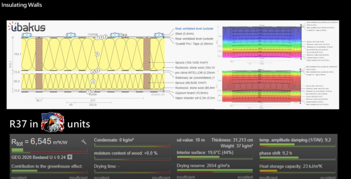
Wall details – Outside to in:
* Steel panel
* 6mm gap created by corrugated polypropylene
* Tyvek Commercial D
* 2×8 horizontal girts attached to posts with blocking, insulated with Rockwool
* Intello air barrier on inside of 2×8 girt wall
* 5/8″ air gap, plywood bracing in some areas
* 2×4 stud wall, 2′ centers, insulated with Rockwool
* 5/8″ drywall with vapor barrier paint
Wall simulation in “Ubakus” tool (screenshot attached). Output was R37.
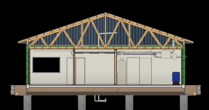
Attic – Blown in R80 fiberglass, extended heel trusses
Slab – 5.5″ inches of EPS. R22 total.
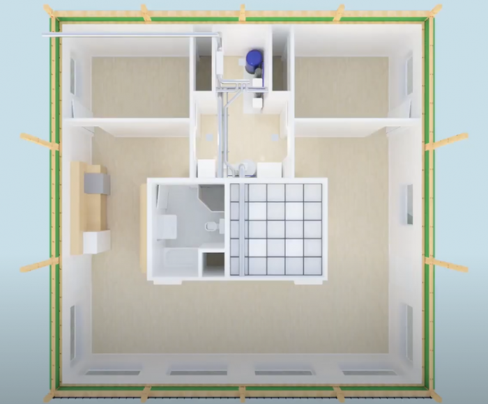
Mechanicals (all electric):
* Two 9k Mitsubishi cold climate mini splits
* Baseboard electric heat backup
* 80 gal heat pump water heater, ducted to pull from main room
* Panasonic Intelli-balance ERV, pulling from bathroom, dumping into bedroom closets.
* Inline MERV-13 V-type filter boxes on HPWH, ERV
* Iron filter, Water softener, CPVC piping
Simulation in BeOpt showed 7k solar needed for net-zero.
Windows: Wasco vinyl windows, high solar gain on south wall only
Building shell will be purchased as a kit, with engineer stamped drawings. Will be doing most of the work myself. Appreciate all the great information on this site. Looking for a last review before I move ahead with the project.
GBA Detail Library
A collection of one thousand construction details organized by climate and house part


Replies
Erik,
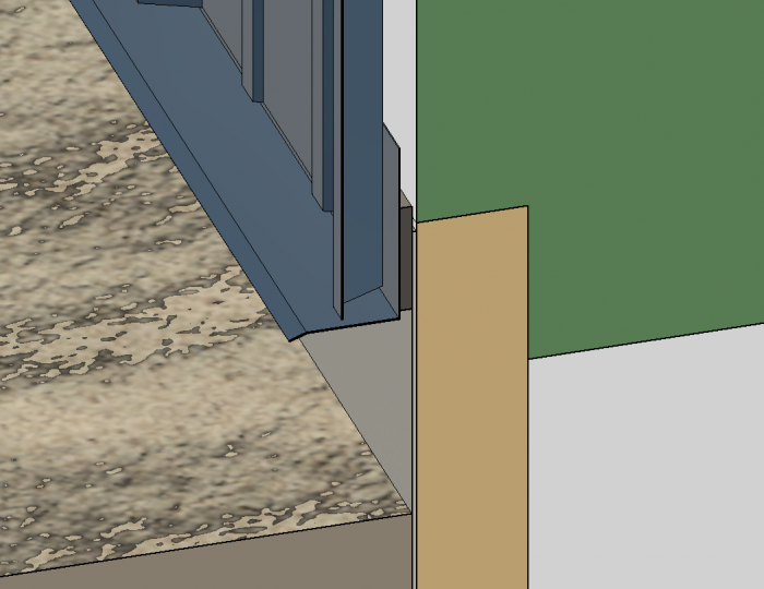
Without wading too deeply through your very detailed assemblies, the one thing that jumps out at me is the base of the steel cladding. Foam closure strips are primarily used to stop water infiltration on roofs. They may also be effective at deterring insects, but won't stop rodents. The most common solution is to use a J flashing at the bottom of the panels to block the corrugations. Is there a gap behind the closure strips which is open to the exterior to allow air movement and drainage in the rain-screen cavity? A detail through the intersection between the siding and protective coating below would be useful.
Hi Malcolm:
Added a picture of the base of the wall steel. Instead of a J channel, there is a drip cap trim blocking the corrugations. Behind the drip cap is the corrugated plastic material, creating an effective gap for air movement and drainage.
https://s3.amazonaws.com/greenbuildingadvisor.s3.tauntoncloud.com/app/uploads/2022/04/19212943/44472_1650418182_drip_cap_-700x540.png
Erik,
Looks perfect to me.
Looks like a pretty solid build. I'm not a big fan of sheathingless walls, it does look like you have though of most details. I would still spend the money on some sheathing though.
I don't think the fans on most HPWH have much oomph. Putting a merv13 filter on it is asking for trouble. Maybe a washable fiber filter.
You want a duct silencer or a length of flex on the fresh air supply of the ERV. Without this you'll hear the ERV when it goes on boost. You can also get a Lifebreath tandem vent for the ERV, single hole through the house and no need to run a duct across the bedroom.
With such a well insulated compact place, a single slim ducted unit in the utility room can heat/cool the place for less money than two wall mounts plus backup baseboards. Also less maintenance down the road.
2x8+2x4 double stud seems a bit overkill, if you have BeOpt set up, I would see what just the 2x8 ends up at.
Thanks for the review of the design.
1. The filter on the HPWH is a low pressure drop V-type. Pressure drop is listed as .12 in-wg @417 cfm. Probably even less at the CFM of the HPWH. Can always put less restrictive filters in the box later, if needed.
https://www.hvacquick.com/products/residential/Filter-Boxes/Inline-Filter-Boxes/AirScape-SFB-V-Series-MERV-13-V-Bank-Inline-Filter-Boxes
2. Have looked at the Lifebreath ERVs, the efficiency is great. However, want to use an ERV with boost as the bathroom vent. Are you suggesting putting the duct silencer between the ERV and the bedrooms?
3. Have considered a single ducted mini split. However, the efficiency hit when simulated in BeOpt was substantial. I like the redundancy of having two identical units. Additionally, this effectively doubles your turndown ratio.
4. I previously had a 2x8 wall only and have simulated it in BeOpt. Going to the double wall cuts down substantially on the thermal bridging between the studs. The outer wall has girts (horizontal studs) while the inner is conventional, effectively making it a "Mooney Wall". Also, the cavity between the two creates a great place for a completely unbroken and protected air barrier.
1:
The fan on the HPWH is probably this one:
https://d12qbzr1dyleru.cloudfront.net/m/a01f2babd9a4e7c1/original/Specification-Sheet-EBM-EC-Fan-Assembly-200mm-W1G200-EC91-10.pdf
0.12" is way too high. You probably need about 1/2 to 1/3 of that.
2:
I meant to use the Lifebreath tandem wall cap with the Panasonic unit. The Panasonic tandem cap is only good for 50CFM. The Intellibalance 100 is great value, there isn't much out there with remotely close to comparable performance for similar cost.
3.
Wall mounts are not zero maintenance. Drain lines clog and blowers get dirty. Having cleaned the blower wheel on my 3 zone multi a while back, I would try to avoid it. Changing a filter is much simpler even if less efficient.
4.
If you must have double stud, I would look at going with either 6x6 posts with 2x6 grits or 6x4 posts with 2x4 grits. Either option would be significantly cheaper and will barely change your overall energy costs.
1. Okay good point, will delete the extra filter on the HPWH.
2. Was confused at first, was thinking "lunos e2". Are you suggesting using the product below? Is there a downside to the inlet and exhaust being so close together?
https://www.lifebreath.com/us/product/ventilation-accessories-dual-hood/
3. I'm okay with added maintenance of the wall mounts. Planning to run the drain lines in PVC to the utility room sink. Drain lines will have cleanouts.
4. I understand that 2x6 girts would be cheaper. However, 2x8 can hang outboard of the 6x6 posts by 1.5" to be flush with the grade board, while the interior edge is clear of the inside of the posts, for a continuous air barrier plane. Also, it's what my post frame kit supplier recommends. Trying to make the build details as easy as possible since I will be DIYing.
Yup that is the part. I hope that there was some engineering put into it to prevent recirculating stale air. I've used the Panasonic ones with smaller ERVs, works great and really simplifies the install. Make sure to account for the pressure loss of the hood, like any wall cap, these do add a bit.
The problem with wall mount drains isn't the drain line but the drain pan. The hole from the drain pan to the drain line is pretty small and since there isn't great air filtering, a lot of dirt ends up in the drain pan. Over time these collect and break off in chunks and clog the drain pan outlet. This is a major design flaw of all wall mount mini splits.