More Guest Blogs


The Department of Energy would like builders to up their game. Though the energy savings achieved by the DOE’s Energy Star Homes program (said to be 20%) is worth celebrating, it’s possible these days to build homes that are even more energy efficient than that. It’s even possible while also delivering other key benefits: improved comfort, reduced water use, the best possible indoor air quality, and the ability to seamlessly integrate a photovoltaic (PV) system. The DOE thinks it’s time for more new homes to take that step.
Enter the Zero Energy Ready Home program. Launched in 2013 as an outgrowth of the DOE’s Builder Challenge program (which saw 14,000 homes certified), this new home certification program requires several steps above Energy Star. According to Jamie Lyons of Newport Partners, a management firm that helps the DOE administer the program, the number of ZERH certified homes has doubled from 2016 to 2018. As of late 2018 there were several thousand certified homes across the country, with approximately 10,000 in the pipeline to be certified.
A new bar for “high performance”
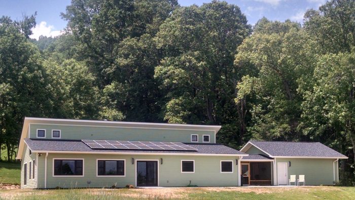
Our company, Deltec Building Company, operates in Asheville, North Carolina (Climate Zone 4A) and surrounding communities. Asheville is a fast-growing area due to the attractive climate and our vibrant arts and beer culture, with a booming construction market and a healthy market for green building in particular. Yet despite the local popularity of green building, no one in Asheville had built a Zero Energy Ready Home until recently.
Since our homes’ HERS scores were already right within the target range (45 to 55, pre-solar), we were ready to try it out. Our energy rater, Dr. Amy Musser of Vandemusser Design, is always up for a new challenge. I just needed to get a willing client on board, and I did so at last when John and Barry, a couple retiring to the area from their longtime home of Chicago, agreed to let their home be our testing ground.
A lot like Energy Star, with substantial add-ons
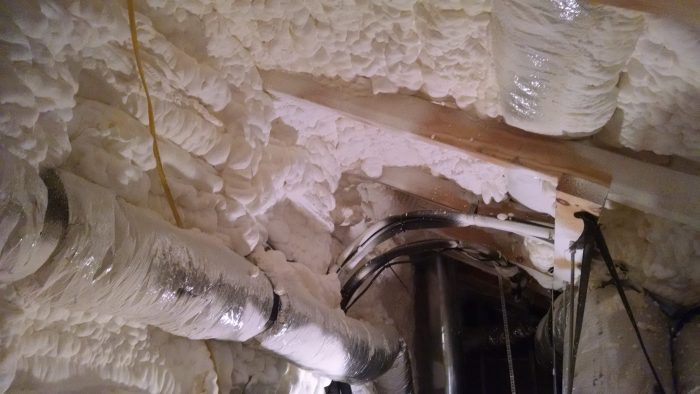
The insulation and comfort system requirements for Zero Energy Ready Home are a bit beefed up from Energy Star, but in our case, we were already doing most of those. The biggest design difference is that ZERH requires all ductwork to be 100% inside the conditioned space, whereas Energy Star merely rewards it. This makes sense, as moving ductwork inside the conditioned space offers notable energy efficiency gains; one study found it can save between 8% and 15% on air conditioned costs.
This two-zone system is our attempt at striking a compromise between right-sizing the unit’s capacity to the house heating and cooling load and the need to distribute the conditioned air effectively throughout the house.
In our area we have seen many contractors who are using minisplits who put one ductless unit in every bedroom, even in very well insulated homes — a design we think is overkill from a capacity and equipment cost standpoint.
The reduced hot water use requirement was the kicker*
There is a little requirement, buried within the ZERH program documents, calling for efficient hot water distribution. The ZERH checklist, V4, states: “To minimize water wasted while waiting for hot water, the hot water distribution system shall store no more than 0.5 gallons of water in any piping/manifold between the hot water source and any hot water fixture.” This requirement must be measured by the rater.
Since most homeowners flush this cooled water down the drain while they wait for the heated water to arrive, this requirement can save a considerable amount of water. Yet a water heater would have to be located close enough to all the faucets to succeed at storing this little water in the piping between them. Having to think about this might be completely new to a builder who has only built for Energy Star, and indeed, is unusual as an absolute requirement for a green building program, rather than an option for additional points.
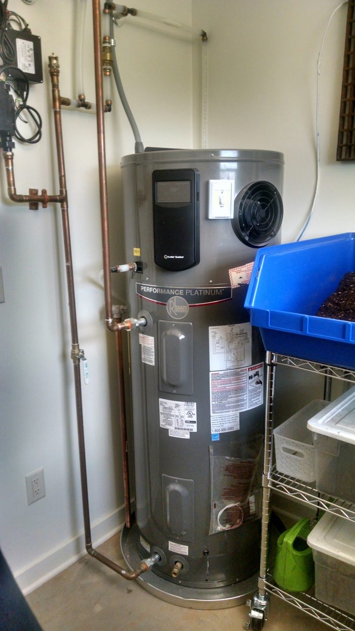
A quick glance at John and Barry’s floorplan had me convinced at first that this project was not going to succeed at this, even if we used a manifold instead of a trunk and branch plumbing design, as the water heater was on the far side of the house from the bathrooms. Yet we had specified a heat-pump water heater for its superior energy performance over a typical electric tank water heater, a technology that John and Barry agreed to despite the operating noise and the cold air, only if they could keep this water heater away from the main living spaces. Since the home was on a slab foundation, moving the water heater under the house to be centrally located underneath the bathrooms wasn’t an option.
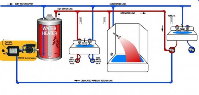
The thing is, for a Zero Energy Ready Home, this pump must be controlled by either a manual button, an adaptive control system, or an occupancy sensor that turns the pump on when it senses someone near the faucet. According to the folks at the DOE, and backed up by conversations I’ve had with our rater, many of the common methods of controlling a hot water circulation pump (such as timers or temperature sensors, or even just leaving the pump on 24/7) end up wasting considerably energy, as the system ends up operating when hot water is not actually called for. Unfortunately all of the circulation pumps that our plumber or their plumbing supply house were familiar with used timers.
Luckily the DOE has some suggestions for recirculating pumps with manual controls. After researching several options, I settled on the D’Mand Kontrol system with user activated buttons.
(*As of 5/8/2019, the DOE released a new revision on the program that has additional options for qualifying for the efficient hot water requirement that were not in effect when we completed the program. However, we think that the hot water re-circulation pump with demand control is such a good idea for situations where compact plumbing is not feasible that we still wanted to share our experience with it.)
A new focus on interior finish selections
ZERH Certification requires that the homeowner also earn Indoor Air Plus Certification, another program available from the EPA with specific requirements for indoor air quality. Many of these requirements also overlap with Energy Star, such as right-sizing your HVAC system with Manual J, installing a fresh air ventilation system, and incorporating key water management details into the building envelope and site grading.
Some requirements were new to us, and required that each interior finish selection be carefully vetted. Any composite wood product (including any cabinetry, sheathing, trim material, LVL, or engineered wood flooring that had a composite wood component), any interior paint or stain, and any carpet and even the carpet pad, had to comply with a relevant indoor air quality standard. While some of these standards were easy to identify (for example, the carpet product the homeowners had already selected had the required CRI green label clearly documented on the spec sheet, and our paint supplier was already using the Sherwin Williams Pro-Mar 200 Zero-VOC line), others required considerable research to uncover.
The interior doors proved the most interesting challenge, as the doors we typically order come from a small regional manufacturer rather than a from national supply house. We uncovered during the vetting process that those doors were in turn assembled from materials purchased from various other manufacturers. Multiple phone calls to various management levels to the manufacturer of each component used by that door supply company, were needed to ensure that the doors were in fact CARB phase II complaint. Even then, it took a special order to ensure that doors arrived on site carrying the actual CARB II sticker so we could prove it to our rater.
“Ask, verify, and then verify again” is a good manta for this kind of product specification research. We were pleased to be able to work with our normal supply companies for our interior products and not disrupt our typical ordering process, mostly because I was willing to put in the research and did so well before it was time to order. Some builders may just want to be sure to order key components from national suppliers who often have better documentation on the various VOC certifications their products hold.
Solar-ready
“Zero Energy Ready Home” is not my favorite program name, I admit. I am skeptical that the concept of “zero energy” would makes sense to most customers and can even sound misleading. (Is it zero site energy? Zero source energy? How is it really zero energy in a typical net-metered situation? What do you mean my home is ready for zero energy but isn’t necessarily zero energy?) I do get it — the concept of being “ready for zero” is about a home that puts efficiency first, so that adding solar is easy and simple.
In our case, solar was already part of the project. Our area has a decent net-metering program, and local rebates for solar offered through Duke Power that the homeowner wanted to take advantage of. Without solar, a home participating in ZERH has to complete a solar-ready checklist which include provisions for planning for future solar.
Benefits and considerations
In the end, the homeowners got a highly efficient home, with tested systems, better air quality, and reduced hot water wait times. We were fortunate that we were able to do so without compromising on the specific technologies (like the heat-pump water heater) or the specific selections (like those cabinets they really had to have) that the clients had had made. Meanwhile, we gained a few new tricks and practices to employ.
The world of voluntary green building certification programs is already a crowded one, and the sheer number of programs to choose from can be confusing for a homeowner or builder to navigate. But having gone through it now, I have to say it that the ZERH program might now be my favorite program. Unlike some of the more complex programs, like LEED or any other points-based system, it’s all-encompassing. Everything is required, nothing is optional — yet the program is simple enough that it focuses on only the best, most universal practices in building science, without getting distracted by other green building practices that are nice to have but may not fit with every job. It builds on programs and concepts that are already out there — like the Energy Star and Indoor Air Programs that are subsumed within it — but takes things further.
I think it’s a solid choice, not just for a “pretty good house”, but maybe even a darn good one.
Leigha Dickens works as a manager of building science for Deltec Homes. This blog is also posted at the Green Built Alliance.
Weekly Newsletter
Get building science and energy efficiency advice, plus special offers, in your inbox.


27 Comments
Congratulations for moving to ZERH and sharing your experiences so more builders learn that its not hard nor expensive to move to a better building system. The same I've found after working with new builders is that all of them find building these homes easier and more cost effective as their competition. Keep up the good work and continue promoting the program.
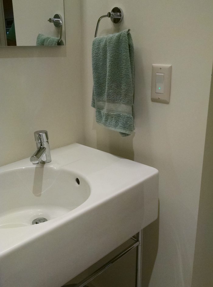
No pipe insulation on that hot water distribution?
https://s3.amazonaws.com/greenbuildingadvisor.s3.tauntoncloud.com/app/uploads/2019/05/21140232/Dickens-photo-3-700x1242.jpg
That would be a code violation- it's not even code-minimum!
IRC 2018 section R403.5.3 prescribes the supply be insulated to not less than R3 if it's 3/4" or bigger. On recirculation systems OTHER than demand types the return side needs to be insulated too, independent of size. (R403.5.3, item 7.)
https://codes.iccsafe.org/content/iecc2018/chapter-4-re-residential-energy-efficiency
I saw that an was briefly hoping that was a mid construction photo, but it looks like the occupants stuff on the shelf.
It also looks like there may be flex duct half buried in spray foam. If you are doing ducts in the conditioned space, insulation should go in before HVAC in most cases. It is just too challenging to spray around things like ducts.
2 minisplits in a high efficient 1700 sf house also has a good chance of being over sized.
Even with rating programs, it is a challenge to get a lot of this right.
Matt,
If I could do it over I would use a different HVAC contractor who was more comfortable making duct runs as short and neat as possible (there was some concern about adequate spacial separation between supply and return air grilles that resulted in some lengthier runs than I'd have liked, in the future I'd probably also minimize returns and do better door undercuts), and I would do the roof SPF first, I agree that's a great idea, and was also one of my takeaways. That particular duct is not actually buried in insulation, the trusses are 16" deep, so there is room to get the R30 behind it which is the local code with a raised heel truss, but it was undoubtedly harder to get the insulation behind it than it ought to have been, and as a whole, I think the flex part of the duct runs do leave something to be desired. (I have definitely seen *a lot* worse, it's a constant pick-your-battles situation. I do wish I'd picked my battles a little harder here.)
As to the minisplit sizing, I am still learning tons (pun...intended?) about this. It seems especially interesting to me in this climate, because we're able to use the hyperheat systems without necessarily having another backup form of heat if we size the minisplits to the heating load. Our heating loads are a rough average of 1.5x our cooling loads, so it is possible with available equipment to strike a balance between sizing the minisplit real close to the heating design load while also keeping the cooling load somewhere in the middle of the cooling capacity range. But sometimes it can be a fine balance to strike.
On this particular project, I do suspect this system might be somewhat oversized, but, not because we used two indoor heads. As indoor heads come in capacities ranging from 6 to 24KBTU, I don't think you can assume a two-head system is oversized just based on that. Instead, in this situation I suspect oversizing partially because the heating load was slightly over the max capacity of the next lowest equipment size (but enough over it that it didn't feel wise to round down and risk heating season comfort complaints), and partially because that load was generated by my HVAC contractor and not my Rater. I don't think my HVAC contractor did a terrible job calculating loads, actually. I've looked over their work on numerous jobs and the basics always seem to check out: house is modeled as tight (though they don't use exact blower door values, since ours are reliably below 1.5ACH50 that would probably help), insulation values and window NFRC info is right, geometry doesn't seem terribly off, but without doing it myself (which I don't have the software for currently) it's hard to know for sure, so I imagine there are likely small things that add up. Interestingly, around the time I was doing this job, I discovered that Energy Star, and by extension ZERH which just references Energy Star in this matter, added an interpretation note that exempts Raters from having to collect load calcs if minisplits are used. This bothers me, and is one of the reasons that on jobs going forward, I've started having my Rater do the HVAC design instead of the HVAC contractor, since she does have that skillset. I have noticed hers tend to be similar to theirs for similar geometry/square footage, possibly a 1/2 ton lower at times.
In my experience, I don't know that I would trust a HERS Rater to design my HVAC systems. They would need to have an extensive training and experience on HAVC systems, and those maybe one in a million. If you don't think your HVAC contractor (or any other contractor) is qualified to perform his/her job right, find a new contractor that does. Its just that simple, and you are paying the bill.
>"I don't think my HVAC contractor did a terrible job calculating loads..."
Really?
I kinda DO think the contractor "...did a terrible job of calculating loads." It's a pretty rare 1700' house that needs 2 tons of cooling, and two tons of hyper-heating ductless is good for over 30,000 BTU/hr @ Asheville's 99% outside designe temp of +16F. Two tons of hyper-heating ductless has enough capacity to heat a tight 1700' IRC code-minimum house in my area down to about -15 F outside. It's it's unlikely that it's been that cold in Asheville recently, and it may not hit negative double-digits again during the lifecycle of the heat pumps. (The last time it was that cold in Asheville was in January 1985.)
But not all hyper heating mini-splits are the same. For the record, what are the make and model numbers of the mini-splits? What were the calculated heating & cooling loads from the contractor (and at what design temperatures)?
>"I don't know that I would trust a HERS Rater to design my HVAC systems. "
That's right.
I also have learned not to trust the average HVAC contractor to calculate the loads, even the typical code min house, let alone a better-than-code Net Zero house.
I believe the average HVAC contractor knows how to calculate, design, install and commission a system, but many don’t do it for laziness and/or dishonesty. At least at one time, most of them were trained to do it right, and doing it right requires more upfront work and may cost less money. Often, HVAC contractors don’t do the calculating and design work until they know they got the job, so they give bids based on past experiences, and what they got away with.
I’ve found that working with reputable HVAC contractors, teaching them about what we are trying to do, and most important, prove to them that you are meeting your envelope and energy loads goals and that you are as much as responsible for the success of the HVAC system as they are, they may be more willing to meet your goals and requests. You cannot expect an HVAC contractor to design a high-performing system when your building envelope is 3-7ACH50 (depending on code), and your energy loads are high. It’s a team concept, not us vs. them.
>" It’s a team concept, not us vs. them."
True, but not everyone got the memo.
It's amazing how much push back I've seen from equipment installers even when the load calculations & equipment have been specified by engineers & architects.
I also see Manual-J reports performed by HVAC contractors on high performance houses that used all code-min inputs (What? A 14" thick double studwall full of cellulose has a different U-factor than 2x6/R20? Who knew? :-) ) with higher than code max air leakage assumptions.
Whenever a Manual-J is performed by anyone (engineers included) it's important to actually READ it with a critical eye, to verify that it bears good resemblance to the house in question and has been reasonably aggressive taking all load reduction factors into account, per the instructions in the Manual.
It's true that not all HVAC contractors are hacks, but experience has shown that it's not safe to assume full competence.
In this case it's possible the calculations were done correctly and the equipment intentionally oversized.
To Armando: Point well taken, in a perfect world, if one sub contractor's not doing what you want, get a new one (if there is one...) I have done that already for many reasons, and the new contractor so far has been helpful in working together to make design decisions in much the manner you describe. His preferred MO, in fact, has been to have us use our HERS rater to do the design, and then work to specify the closest system and make the judgement calls together when things are on the line. However, my HERS Rater also has a PhD in Mechanical engineering, so I'd say she is qualified to do load calcs. That's not the average for most HERS Raters, to be sure. One unexpected advantage to me of this approach is that I don't have to spend as much effort getting ahold of the Manual J anymore because I'm the one who is hiring the Rater to give it to me. Though I was always asking it of the old HVAC contractor, and they did always give it to me, they did get slower and...slower...about it, and when I learned Estar no longer required it to be collected for minisplits I was concerned I'd lose that piece of leverage over them for obtaining it.
Dana: No, we've not seen double digit negative air temperatures in my lifetime (I'm dating myself), but we've seen extended periods of single digit lows fairly recently, and we're in the mountains, so we build in some higher elevation micro-climates that will see much colder air temps than Asheville Airport. That house is not at a high elevation though, so me saying that still becomes another example of the bad habit of fixating on the the extremes and not the design temps, which is a fallacy I wasn't trying to go down with this project. I appreciate your shared experience of using two-ton minisplits for similar homes in much colder climates. It seems like that's great anecdotal evidence that it would have been perfectly safe and wiser to have rounded down on sizing.
The equipment is Mitsubishi, outdoor model MXC-4C36NAHZ, with a branch box, a ducted SEZKD18 and an ductless MSZFH15. I admittedly don't know much about the branch box aspect of this. The heating load from the HVAC contractor came out at ~30,000Btus/hr, which as I understood it was enough over the max capacity of the next lower size, the MXZ3C30 which only offered something like 28,000Btus/hr despite being called a "30", that it wouldn't have be enough for the heating load w/ no backup. But considering the possible over-sizing of their calcs, and the safety factor built into Manual J to begin with, it likely would have been better to round down. One tool that I have now, that I didn't then, is Mitsubishi's Diamond System Builder software, which lets one build the system and see the expected capacity of each indoor unit at your local design temps when factoring in your exact indoor/outdoor unit pairings, the lineset lengths, bends, etc. Ostensibly that's part of what they did, but I didn't get to see it, so with the system builder software, I can now see that part for myself.
So, since sizing limits aren't even enforced by Estar/ZERH in the case of minisplits, what *would* be the best way for a builder relatively conversant in the concepts to tackle this? I did actually read their manual J for mistakes in representation of insulation, windows, and air-tightness, and if it fell down, it probably was around air-tightness. I took a glance at the window areas but I didn't double check all their geometry math--at some point, you're just redoing so much of the work it would probably be simpler to do it yourself. (Which, I ultimately will learn to do, but I'm a building scientist working for a builder. The average builder probably hasn't got the bandwidth.) Or, hire a consultant to do it? The "hire a consultant" approach seems the best short term option to me.
As discussed by Dana. You likely need to wrap your head around how little heat these homes (or even a code min home) really need. Particularly at the balmy design temps where you are at. Manual J even done right is pretty conservative and doesn't take credit for an thermal mass or solar gain.
The advantage of a single ducted head vs adding another head to make a zone is that you get a lower low modulation level of heat, making the system generally more efficient. In the case of the Fujitsu mini duct systems the minimum modulation is 3000 btu/h for all the sizes, so there is only minimal downside to bumping up a size to cover the removed head.
That's interesting, I didn't know that about the Fujistsu models. For the Mitsubishi the lowest modulation does vary based on the head size, and with the multi-zone system, I recently learned it's just 30% of the max capacity of the outdoor unit, whatever it is.
Still, it's tricky, because 3,000btu/h in each bedroom is still going to be oversized, and it's a question of effective distribution vs capacity. The risk is that if you don't do the distribution part well enough, some client, somewhen, is going to be really, expensively mad at you. (Maybe they're the ones who move here from Florida and don't think we're quite "balmy." Or the ones who move here from cold climates and don't understand heat pumps.) I know there's all kinds of strategies for dealing with this with ductless units only: leaving doors open, transfer fans, jumper ducts, etc, and we've done some experimentation with that, and I think I should do so more aggressively. But I'm still learning how to gauge when a client is just going to be really unhappy with room to room temperature differences or a strategy for managing them that doesn't match the lifestyle they'd envisioned.
Dana,
Well...good catch! The hot water trunk line and return loop *are* actually insulated, this was verified at a sub-slab plumbing inspection that I did with the Rater to help us both make sure the re-circulation loop in the slab was being installed correctly. But yes, clearly we missed the section of said loop that was inside the utility room. I'm sure this occurred because hooking up the water heater was a separate trip with a different crew from the plumber, and in my focus to make sure the plumber got the thing hooked up right in the barest sense (there was some consternation about a new system, to be sure), that particular detail escaped me. However in my defense, North Carolina isn't on the 2018 IECC, our state has historically created our own (watered down and confusingly hacked up) version of older IECC editions. That home was permitted on an edited version of the 2009 ("North Carolina 2012"), which only stipulates "R2 for hot water re-circulation systems." But sure, that R2 ought to be on the entire length of the the pipe. I can fix that.
I meant this to go as a reply to Dana's first comment and somehow it got out of order, hmm.
Comments are nested, so all replies to comment #3 will appear before comment #4, regardless of when they are posted.
>"R2 ought to be on the entire length of the the pipe. I can fix that."
The IRC calls out R3 minimum, which isn't really going to be more expensive than R3 for pipe insulation at domestic hot water temperatures. Even 3/4" wall thickeness R5 pipe insulation isn't much of an upcharge.
Even if R2 is technically allowed under local code, going with code minimum on anything wouldn't seem to be in keeping with the theme of this house.
Do you calibrate the system so it knows how long to run the pump based on which switch was pressed?
Reid, I believe those pumps have a temperature sensor that determines operating time.
Right, the D'Mand system we used has a temperature sensor. There's nothing about calibrating the system in their installation instructions.
Is there a temperature sensor for each room, or is the temperature sensed at the pump. If it is sensed at the pump, then you are filling up the entire hot water distribution system plus the return line. That could be considerably more hot water leaving the hot water tank than when you just run it down the drain until it is hot. (I know I am ignoring behavioral waste where the person goes and does something else instead of standing there waiting. Also, the energy waste per gallon of water leaving the hot water tank is less with a circulation system because the water going into the hot water tank is not as cold.)
The temperature is sensed at the pump, so yes there is energy wasted on the hot side but not the cold return. But the intent is to save water, not energy. Of course, when you save water you are also saving the "embodied" energy it took to purify it. Continuously circulating systems clearly use more energy than demand systems.
Not sure what you mean by not wasting energy in the cold return. It looks like the pump is at the end of the cold return, so the cold return would get filled with hot water before the sensor located at the pump would detect it.
I understand that there are places in the country where saving water is important for its own sake apart from saving energy. I didn't realize that North Carolina was one of those places. I suspect the true value of the system is convenience for the user rather than saving either energy or water.
>"The equipment is Mitsubishi, outdoor model MXC-4C36NAHZ, with a branch box, a ducted SEZKD18 and an ductless MSZFH15. I admittedly don't know much about the branch box aspect of this. The heating load from the HVAC contractor came out at ~30,000Btus/hr, which as I understood it was enough over the max capacity of the next lower size, the MXZ3C30 which only offered something like 28,000Btus/hr despite being called a "30", that it wouldn't have be enough for the heating load w/ no backup."
The 3 ton MXZ-4C36NAHZ is good for 45,000 BTU/hr @ +5F, and at +17F, so even if the load calculation were correct the compressor is 1.5x oversized for the load.
http://meus1.mylinkdrive.com/files/MXZ-4C36NAHZ_Submittal.pdf
The MXZ-3C30NAHZ is good for 28.6K @ +5F & +17F, barely undersized for a 30K load (two sleeping humans, an alarm clock and maybe the water heater would make up the difference):
http://meus1.mylinkdrive.com/files/MXZ-3C30NAHZ_Submittal.pdf
With the SEZ KD18 there is potentially some capacity derating that has to take place, especially if any ducts go outside the insulation & pressure envelope of the house, but even then I suspect even the 3C30 is something like 50% oversized for the real load.
Following the short-version capacity calculations on page 4 the 4C36NAHZ the heating capacity of the SUZ18 is 17.2K and the heating capacity of the FH15 is 15K, which adds up to 32.2K. Since that is less than the max capacity of the 4C36NAHZ, they need no further derating, assuming there aren't parasitic loads from ducts outside the building envelope.
If there is only 32.2K of cassette/head capacity and the design load is REALLY 30K, there isn't really any margin to speak of to cover for the additional load at temps much cooler than the design temp. The total cassette capacity to design load ratio is only a 32.2K/30K= 1.07x oversize factor. An extra 7% is not very much for "no backup", despite the much larger capacity of the compressor. ( A 750watt plug-in space heater provides more backup capacity than that.) To max out the compressor's capacity there would need to be more head/cassette capacity.
But since the REAL load is probably less than 20K at design temp, it's probably covered down to negative double-digits outdoors.
It's EXTREMELY unlikely that the heat load is actually anywhere near 30K @ +16F or whatever. That would be over 17 BTU/hr per square foot, for a better than code house with a very clean, simple shape and favorable surface area/floor area ratio. Most tightened up 2x4 houses can hit that mark at sub-code insulation values.
As crummy as BTU/ft^2 rules of thumb are, typical code-min houses in my area regularly come in with load/floor area ratios between 12- 15 BTU/hr per square foot @ 0F. That would make this house about 25K @ 0F (give or take) if it were built to zone 5 code-minimums, and substantially less at mid-teens design temperatures. With a better than code house it should be lower still.
For reference, I live in a 2x4 framed 1923 vintage sub-code 2400' antique plus 1600' of (insulated) basement, with mostly antique single pane double-hungs with clear glass 1980s vintage storms, and a few 1990s vintage clear glass double panes, and 14 corners to the footprint of the house. MY heat load at +17K would be pretty close to 30K (confirmed by both fuel use and Manual-J). I'm radiation limited to about 44-45KBTU/hr, and this house sees negative double digits every few years without comfort issues. (Local outside design temp is +5F.)
The Asheville house is much more efficiently shaped than mine, with better insulation & windows, ~30% smaller, with far less exterior surface area. There's no WAY it should have a comparable heat load to mine. Something in the Manual-J has to be off.
Reid, you are mistaken. The pump is located at the point of use, typically in a base cabinet.
Historically Asheville has been in a high rainfall area, so the value of the system is questionable.
OK. I was looking at the schematic which shows three separate switches, presumably in different rooms, and one pump located at the water heater. I thought the stuff at the upper left of the photo of the water heater was the pump.
That schematic is confusing. A better one is at http://www.gothotwater.com/sites/default/files/Exisisting%20Homes%2051513.jpg .
Isn't that the pump located to the left of the water heater? That would indicate this is a structured plumbing setup with a dedicated return line.
Yes, what Leigha included shows the pump near the water heater. But I don't know why you would set it up that way if you can get a better result without the dedicated return line.
Log in or create an account to post a comment.
Sign up Log in