Resource for Calculating Cantilever Joist Lengths
I’ve found charts that show max cantilever lengths for decks, and some info for bumpout additions, but I’m not sure whether what I’m trying to do is a bit different, and would like help on finding the correct tables/charts…
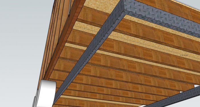
I’m cantilevering the entire load bearing walls of a 10’x28′ house on an 8′ wide trailer, so 12″ of overhang on either side, and I need to figure out what size joists I’ll need to support this. (See pic) The roof is going to be designed for 60psf uniform load, and at either end of the house there will be a loft, so a 2nd story, though not too significant since it’s a “tiny house” at only 10′ wide.
The bumpout addition rule of thumb seems to be that you can cantilever up to 4x the depth of joist, but I don’t know if that applies here.
GBA Detail Library
A collection of one thousand construction details organized by climate and house part


Replies
skibow,
Here is what the OBC says:
The Ontario Building Code | Cantilevered Floor Joists
9.23.9.9. Cantilevered floor joists
(1) floor joists supporting roof loads shall not be cantilevered more than 400 mm beyond their supports where 38 mm by 184 mm joists are used and not more than 600 mm beyond their supports where 38 mm by 235 mm or larger joists are used.
You are fine with 2"x8"s, and given the short spans I would be comfortable using 2"x6"s.
How high are the walls? That sounds like it might be a pretty tippy trailer.
Thanks for that, sir. I’m only in the beginning stages of planning, but I think around 12’ tall walls if my memory is correct. Max roof peak height is 13.5’. 4/12 single pitch with a metal roof along the entire thing is the plan - to keep the lofts somewhat livable, yet still hopefully shed some snow - though I don’t mind shoveling the roof on such a small structure.
I don’t plan to move it often, only if/when completely necessary. This cantilever-by-a-foot thing seems to be pretty common in the tiny house building world, so I trust that it won’t tip. I did have to ask about the floor joists given that most of these homes aren’t dealing with snow loads and/or the building specs aren’t the main point of conversation.
Thanks again!
I have a house and a garage with metal roofs. You do NOT want to be up there when there is snow, or even dew on the roof. Do NOT count on being able to shovel it.
Also: I had one of these cheap pole and fabric shelters. Oriented east west. Warm day, Snow slid off the south side. Reaction force collapsed the shed north.
I've seen a video of this happening to a large metal building (mining camp, processor building.
Strongly suggest that you raise the pitch so that it sheds more regularly. The loft of our house has a 1 in 4 pitch, and doesn't shed enough, and when it lets go the whole house shakes. I'm looking at putting snow stoppers on it, so it has to melt off.
Another issues is anchoring. When the snow slides, if there is a strong lateral force can it tip the trailer over? Two thoughts.
A: Have some form of ballast. Drums that can contain water?
B: Carry the heavy duty tarp/fence corner anchors sold by farm stores
Also: For winter, park the trailer so it's axis points SW, This is more likely to trigger symetric slides, (Warmer in afternoon. )
The tricky thing about using residential codes for trailers is that codes usually don't account for the effect that bouncing down a bumpy road will have on the structure. When I have designed travel trailers, I incorporate details from the high-wind-zone and seismically-active zones in the code books, and it still makes me nervous so I no longer design them.
In your case, with a 60 psf design load for the roof plus let's say a 30 psf design load for the loft, the total design load is about 90 psf. (We could parse it more finely if needed.) With 16" o.c. joists, a 1' overhang and a 10' wide roof, that's about 600 pounds pushing down on the end of each joist.
That's for a static load. With a dynamic load, you have to add a safety factor. Engineers would likely use up to 3X the design load. I'll be less conservative and say that maybe adding 50% to the design load is safe enough. I really don't know, but for calculation purposes, let's say the adjusted design load is 900 lbs of downward force at the end of each joist.
Using the engineering calculation for bending moment--similar to torque--you have about 900 ft-lbs of bending moment acting in the joist. (The 10' trailer width and 1' overhang makes the math relatively simple.)
You can use a calculator to determine the extreme fiber in bending--i.e., will the joist bend so far that it breaks? https://www.calculatoratoz.com/en/extreme-fiber-stress-in-bending-for-a-rectangular-timber-beam-calculator/Calc-4425.
For 2x4 joists, the calculator shows extreme fiber in bending of 110 psi. Bumping up to 2x6s results in extreme fiber stress of about 44 psi. Typical softwood framing lumber can handle 725 psi, so you are well within the limits even with 2x4 joists. In other words, even 2x4 joists would handle a 1' overhang .
Another thing to check is how large the floor joists need to be to support the regular floor load. At 50 lbs/sq.ft. with 16" o.c. joists of typical framing lumber, you would need the joists to be at least 1.5" x 5.4", or basically 2x6s, which also meet IRC requirements. I know in a trailer like yours, height is a major constraint; you might want to consider changing to LVL joists so you can get away with 3.5" tall joists.
One more engineering item to consider is crushing perpendicular to the grain. You have about 1,000 lbs of force at the cantilever. Framing lumber can resist somewhere around 350 psi of force perpendicular to the grain, so you need at least 2.85 sq.in. of bearing. With a 1.5" joist, that would be 1.9" of bearing--more than you probably have with the metal frame alone. On a past project, I designed 2xs to be bolted to the trailer frame, in part to help with bearing area. LVLs have greater resistance to crushing and would probably be ok bearing only on the trailer frame.
Yet another thing tiny-home builders rarely think about is protecting against lateral movement--i.e., including one or more shear walls in the design. You can see one way I handled that in the attached drawing.
Michael, thank you for that very clear, detailed reply. I'm just a newbie and that all made perfect sense. Upon refining my sketchup model, I now see that my trailer-cantilever will be only 9" rather than 12" (now that I've added cladding, exterior insulation, eave overhang, etc) to stay within my 10.5' overall width. I did some rough math on LVL, and the price increase isn't too bad considering it's a relatively small project - so good call there, too.
It looks like the trailer I'll be ordering uses 2" wide C-channel, so 2" of bearing surface.
I would make heavy use of steel strapping at connections too. Hurricane ties, that kind of thing. Regular houses generally don't have to deal with uplift forces -- forces that "lift" parts of the structure causing nailed connections to separate. Hurricane ties and steel strapping deal with those problems, but in your case the uplift forces are from bouncing down a road instead of extremely high winds.
It probably makes sense to use structural screws in key places too and not just nails everywhere. You don't want any connections pulling apart as you bounce down the road. Remember when you use strapping to wrap around corners and tie vertical pieces together in a straight line. The goal is for the strapping to keep all it's fasteners in shear, so that there are no forces acting to pull any fasteners straight out.
BTW, as an engineer, Michael's potential safety factor of only 50% makes me nervous. Wood is a natural material, meaning it has a lot of variation in specs from piece to piece. You can minimize that somewhat by using MSR (Machine Stress Rated) lumber instead of the usual visually graded stuff, but doing that adds cost. You might consider using MSR lumber in key places though (outside corners, shear wall bracing, any other potentially high-load areas), but I'd still use at least a 2x safety factor here. Another option would be to have a steel fabricator weld together a base frame for you so that the wood joists don't have to carry all the load alone. Steel can do more in less physical space, and welded connections don't have the same issues with vibration as nailed/screwed connections in wood do.
Bill
Good points, Bill. Here are a couple more screen shots showing some of the hardware I had spec'd. I don't recommend using my specs; I do recommend that builders of tiny homes on wheels consult with licensed engineers to work out their own, safe details.
Michael, rather than using red loctite, I would recommend a nut/split lockwasher/ jam nut assembly. Sometimes you can get by without the lockwasher, but I like to use one in high vibration environments for some extra insurance. A jam nut is like a thinner version of a regular nut, around 1/2-2/3 the thickness of a regular nut, and it's purpose is to be tightened against a regular nut to "jam" it in place. The combination acts to keep a nut in place on a threaded rod. I have used this arrangement many times on pipe hangers for large (16" plus diameter) chilled water lines.
Note that "threaded rod" isn't super strong as far as tensile strength goes. You can specify grade 5 threaded rod if you need something beefier, although it's probably not really necassary in this type of application.
BTW, I like all the "this over that over the other thing over the first thing" stuff :-) I humbly suggest a callout drawing with an enlarged detail to make those complex assemblies a little clearer. I'm always looking for ways to avoid errors on projects, and errors often come from confusion, so making drawings as clear as possible is always a good thing!
Bill
Bill, thanks for the feedback. These drawings are almost ten years old for a trailer that was never built. I stick with regular houses now. For a year or two long ago I worked with a rigger at a boat yard and learned a lot; that's where the red locktite note came from.
Bill, I'm definitely going to be using steel plates at connections. Not only could there be bumps in the road, but the constant wind and gusts when driving down a highway.
Michael, can you recommend any licensed engineer(or how to find one) and give a ballpark figure of what it costs to work with one for a project like this? I put the "green" in green building advisor ;)
Engineers are licensed by state; I would look for one in your area. Some are more creative/less rigid than others; I would ask builders, architects and others you might know to recommend one on the creative side. Costs will vary; somewhere between $1K and $10K, depending how much work they do.