Improving Smart-Tech Capabilities of an ERV
Hey all,
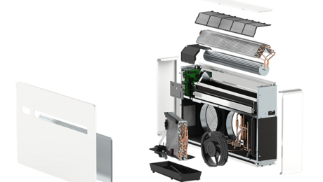
I thought I would share my experience trying to make my Panasonic Intellibalance ERV smarter.
If you were like me, and saw the Panasonic ERV promoted by Matt Risinger on his Build Show (https://www.youtube.com/watch?v=L7XeULkcnpA) you probably decided to make this your ERV of choice. He is a great salesman and promoter. This ERV is an incredible bang for buck on performance. It has a sensible heat recovery of 80%. I got it direct from a supplier here in Chicago for about $900.
My biggest complaint after using it for over a year now is that it is a little light on the controllability and smart features. But to get all those things, a nice app, good data trending capabilities, and ~ 5-8% better performance, you’re looking at a Zehnder, which is 3-4x the cost (maybe even more).
We installed the 100 CFM unit on our second floor to ventilate our bedrooms and home offices. It has been running continuously 24/7. I also monitor our IAQ across the home and have seen consistently low CO2 readings on the second level where this ERV is ventilating. Our master bedroom CO2 over night, with the door closed, 2 humans, 2 dogs, very rarely peaks 600 ppm CO2.
I wanted to explore dialing back the ventilation, but my only way of controlling it was through a smart plug that could give/cut power. I recently found out that when you cut power to the ERV, the outside dampers stay open and the core becomes susceptible to freezing. If you keep power to the unit on continuously, and utilize an on/off switch instead, when the unit is told to turn off, it auto closes the dampers. I also wanted to explore the boost mode switch too, so that I could turn the typical operating CFM down to minimum (50 CFM) and have the ability to ramp up airflow when there was an indoor air quality event detected.
So how did I do this?
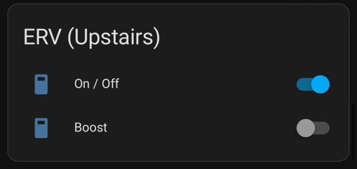
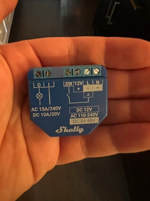
I purchased 2 Shelly 1 Plus smart relay switches. I wired each Shelly relay to the ERV control board to control the on/off switch and the boost switch. Each switch is now digitally controllable in the Shelly app, but more importantly I am integrating all my smart devices into Home Assistant.
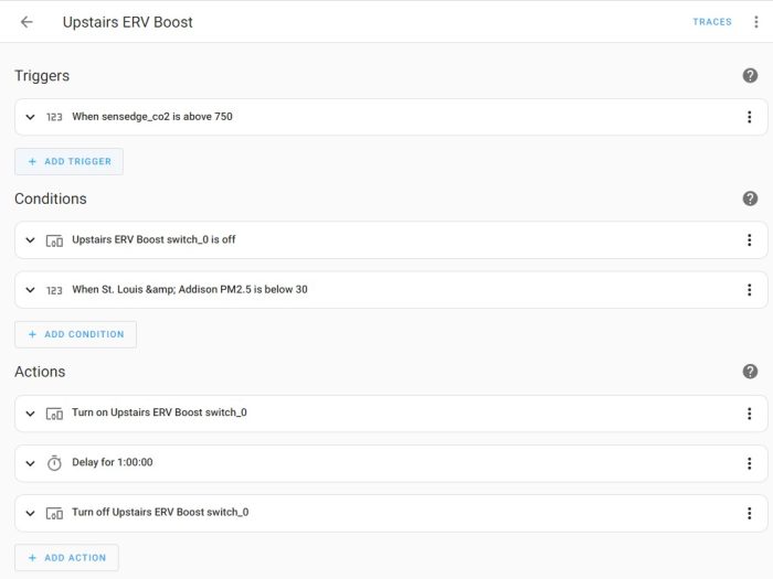
Within Home Assistant, I can write detailed control sequences to operate the ERV. The current sequence I created (attached) is about turning on the Boost Switch ON when a specific CO2 threshold is surpassed. This will run maximum airflow for 1 hour. I’m also able to include specific conditional statements, for example, if the boost mode is already on, it will not run the sequence again, but more importantly – it will not boost if hyper local outdoor PM2.5 is above 30 ug/3. I am trying to integrate ozone readings as well, but finding a free weather service that has that on their API has been challenging. I could also set a condition for outdoor dewpoint as well. The options are endless!
I hope this has been helpful for anyone who has a Panasonic ERV or similar looking to make their controllability a little smarter.
Thanks
Scott
GBA Detail Library
A collection of one thousand construction details organized by climate and house part


Replies
+1 for HomeAssistant. Any feedback on Shelly vs FortrezZ products? I was going to go with HA + Z-Wave hub. Do you have any other products on Shelly's platform that made you decide to go with that system?
Hi Matthew,
No other products from Shelly, but after doing some (light) research on the Home Assistant community boards, Shelly was a clear favorite for smart switch relays.
I bought a 4 pack from Amazon, they came out to be about $12 each delivered.
The install was super easy. Home Assistant automatically integrated them, I did not have to do anything, which is always amazing.
I am not currently using any z-wave or zigbee, on wifi specifically at this point.
Scott
@chicagofarbs, I agree that ERV/HRVs could be a lot smarter yet :-)
You may get a few more ideas from this thread:
https://community.hubitat.com/t/success-0-10-volt-control-of-ac-infinity-or-any-ec-fan-motor-using-leviton-zs057-d0z-zigbee-dimmer-or-zooz-zen54-zwave-0-10v-dimmer/104450/8
I took things up a few notches by gutting an HRV, and installing two ECM fans, both controlled by 0-10V Levition ZS057-D0Z dimmers. This way I can adjust balanced airflow profiles from 50CFM to 110 CFM in 10 CFM increments based on CO2 levels, VOC, and Radon. The kitchen exhaust fan is also automated via the induction cook top, 0-10v controlled, and integrated with the HRV system for supply air.
You've labled the Co2 sensor "SensEdge" sensor. Did you role your own, or this an off the shelf sensor? I'm using an Ecowitt WH45 CO2 sensor (highly recommended), to manage air flow dynamically based on CO2 levels combined with two AirThings Wave Plus which provide input to the Hubitat hub. The HRV is driven by the three Co2 sensors (one on each level) averaged level with overides for VOC, Radon and kitchen exhaust supply air. Because integrations are already there for Hubitat I'm assuming some one has done similar for HA.
I've been down this rabbit hole for a year now so have refined the system extensively integrating dynamic inline heating, supply air, Radon and VOC routines. I also vary the defrost times dynamically based on outside temp vs just using standard times as everyone does. This reduces the time in defrost mode to exactly what is required for a given temp.
You can add temp probes to the four airstreams using a Fibaro Smart Implant and cheap DS18B20 temps sensors. This way you can monitor dynamic efficiency, something I've found quite educational as you monitor the efficiency plummet at max flow. Because I'm also using inline PTC heaters to bring up air temp, Iv'e become very aware of the actual cost of running the unit, and the energy savings in keeping ventilation rates only as much as needed.
When you run the Panasonic 100 at max air flow, your efficiency is likely dropping to the 60-65% range, which is fine, unless you're in zone 7A as we are :-) That said, you can dial it in as you experiment a bit to reduce your "on boost" time to minimum.
Hi Dennis,
Thanks for sharing your advancements!
I have 12 different IAQ monitors throughout the house that I can tap into through Home Assistant and use those reference points as triggers. I have 3 Awair Elements, 1 Kaiterra Sensedge, 2 Airthings View, and a few Amazon IAQ monitors. Sounds like the integration capabilities are the same between HA and Hubitat Hub.
Next steps is to get temp/rh probes, I would love to have that real time monitoring just like Zehnder provides.
Hi Dennis,
I read through your hubitat post and it triggered an urge to smartify my ERV as well -- I'll start by reading the airstream temps by wiring a DS18B20 up to an esp8266. I am curious on were in the supply you ended up placing your PTC heating element and how you mechanically integrated it into the ductwork.
@chicagofarbs , that's a log of IAQ sensors! I use the temp probes to mange a few things, aside from the efficiency information. For one thing, if the fresh air temps stay too low for two long, (has happened in -35 C) the system shuts down for an hour to warm up. Managing the defrost times dynamically via an equation has been a bit of a tuning process, but it works very well.
I've attached screen shots of the dashboard which has grown a fair bit over the last year..ha.
@tobym, there are two PTC elements in the air stream in a custom built metal duct, after the inline filtration on the fresh air side. I've included additional safeties to the heater integrated snap switches with a Honeywell remote bulb thermostat (cuts power if housing exceeds 70 F), as well as a thermal fuse in a metal junction box on the housing. I figure three levels of safety is a good thing. The heaters are controlled by two Zen72 dimmers (one for each) and the heater level is calculated based on CFM, air temp exiting the HRV, and then the target delivery temp. I tested the dimmers at levels from 0-99 to determine the actual watts used by the heaters and then sorted a basic equation to use the current CFM settings, and wattage to get to my target temp. It works amazingly well. The Hubitat hub re-calibrates the heater settings every time the fresh air (unheated) temp changes. The system turns off the heaters when inside temps indicate our high efficiency fireplace is in use, during defrost cycles, and when the delivery temps are at or over 65F. This is important in my application as this system is standalone and all fresh air is dumped into the main living area.
Here is a screenshot of a portion of my Home Assistant where I am tracking: hot tub heating automations, ERV switches, light switches, CO2 across the house, main floor thermostat, utility real time pricing per kwh, hot tub status, hot tub controls, outdoor air quality, humidity across the house (which I should recalculate to dew point).
Scott; that looks very comprehensive :-)
@tobym, I basically graphed the relationship between the Zooz Zen72 dimmer settings and measured wattage used by each heater. Then pulled an equation from that line. Assuming that the heaters are close to 100 percent efficient (and they are) then you can assume that watts in is directly related to the increase in air temperature for a given CFM.
dimmer setting = .122 * (((CFM Variable x 1.08 x (68 - Fresh Air temp))/3.41)/2) + 16
Given a few conditions, the Hubitat hub dials in the two Zen72 dimmers based on the equation above. I was honestly surprised on how well this actually works to keep fresh air delivery temps pretty much exactly on target. “Fresh air Temp” is in F and the CFM variable is actual CFM. That variable is reset anytime the fresh air fan speed changes via the 0-10V control. In that case I’m just using a basic table where the 0-10V signal (0-99) sent to the fan is mapped to a set CFM which was measured at the HRV itself using a differential magnahelic gauge. Each CFM setting (from 50 to 110 CFM) represents a Hubitat scene with Fresh air and Exhaust fan settings based on balancing again done at the HRV for each of the six ventilation rates.
Normally you would just balance at high speed, set the dampers and leave it but when using ECM fans you can balance to any air flow you want and dial stale air/ fresh air fan speeds as needed. The total system power use at 90 CFM is about 45 watts, excluding supplemental heat.
Another benefit of controlling the ECM inline fans via 0-10V that I can toggle up asymmetric flow and supply an extra 50-100 CFM (positive pressure) when the kitchen exhaust is running. The kitchen fan speed (inline ECM, 0-10V control) is set according to power use of the induction cooktop, a great way to minimize fan noise, while ensuring near 100% capture at the cooktop. That system runs itself and has worked surprisingly well over the last year in service.
@Dennis, would you ever consider jumping to open source Home Assistant over Hubitat? If not, why?
It's just a time thing. I moved from ST to Hubitat, and spent a lot of time resetting devices etc. Once Hubitat took on Webcore, then it was a lock as I use Webcore for solar heating management. I should play with HA at some point, but again..time. Rule Machine (in Hubitat) is pretty clunky for equations, but it has been reliable for local control of everything. I have a CS8 hub as a spare, and Hubitat allows a free cloud upload for backing up of the C7 which will restore all zigbee and zwave devices without resetting etc. to the CS8. In other words, at this point, there is no incentive to change anything as porting all the rules over etc. would be very time consuming. Attached is the rule set that controls the house ventilation. It was important that HE could manage evaluation of equations as this is what governs the modulating defrost schedules, modulating heating system, live efficiency calcs, CO2 averaging, etc.
We had a situation last winter in -30C where the exhaust port was frosting up to the point of restricting air flow. This showed up as a dramatic drop in efficiency as the HRV core was unbalanced. The easy fix was a rule to run the system at full exhaust (while leaving the defrost damper open) for a few minutes each day at 2pm (when the south side is the warmest) to melt any ice accumulated at the exhaust hood. This is one of the many examples I think where a "smart" ERV/HRV with probes in the four air flows does a far better job at sorting issues, saving power etc. vs what's out there currently.
@Dennis thank you so much for all the great and detailed information. I had a few minutes today and got started on measuring my ERVs stats -- I soldered 4 temp probes to an esp8266 board, printed a case, and found a spot inside the ERV. I didn't feel like drilling into the ducts, so for now, I just placed a temp probe on each of the four sides of the ERV core. I am pulling the data into HA and can calculate efficiency -- thanks again for your screenshots. The next step will be to hook up a relay to allow switching into boost mode. I have a Broan ERV and there is some limited info on the web from people trying to reverse engineer the controls, but as a start I should be able to hook the relay to the OC/OL contacts and switch it into boost.
@Tobym, brilliant! My one comment on the probe location is that your values may be skewed right now by the heat generated by the motor (likely not a huge skew) so you may find these values change a bit if you move the probes into the ducts. Those temps/efficiency look great. I'm guessing the air flow during that screen grab is fairly low? I like that you included the recovery BTU.
The efficiency number, assuming the unit is not in a defrost cycle, is a good way to check for exhaust hood frost build up at very cold temps too. It will drop (potentially a lot) as exhaust is obstructed.
There was only one ERV that I have come across (they are no longer in business) in the past that exposed 0-10V control for the fans, so you're right in that a relay on the boost contacts is probably your best bet with the Broan unit.
For my setup I open the OC/OL relay to force defrost mode (doing this closes the defrost damper) and close the relay for normal ventilation. I'm just using the relay on the Fibaro smart implant for this, along with 5 of the 6 possible temp sensor inputs. The factory wall control is set to off, so the automation system can effectively control both defrost and fan speed, necessary in my case with the OEM motors removed internally.
If you took any pics of your setup, please post them. That ESP board looks like a great solution for "roll your own" automation.
@Tobym , you had me curious on adding a few more data points. Adding the actual watts for exchanged heat and added heat is interesting. You can really see the value in having a more efficient core in an HRV/ERV. I'm at 79% efficiency and recovering 567 watts in the HRV core, but still adding 147 watts to warm the air to room temps after the exchanger. The system has dialed in 50 CFM (low occupancy currently) so this efficiency only drops as the air flow ramps.