Multi Split and Remote Wall Thermostat Temp Sensing
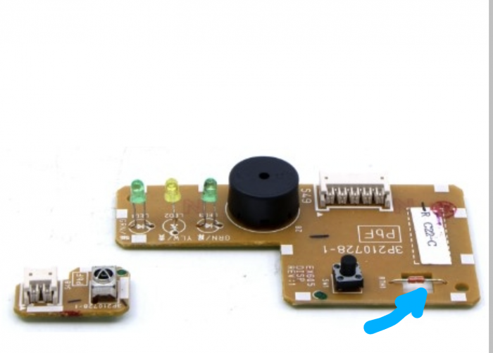
Can anyone weigh in on my thoughts here and let me know if I’m missing a better opportunity. I’m thinking of extending the room temperature sensor/thermistor (blue arrow in attached image) in the head by wire and routing it to a better physical location. As opposed to buying the expensive central thermostats from Daikin which I’m not positive read room temp from their location and then provide that info to the head.
I have a 5-zone Daikin 5MXS48TVJU outdoor unit paired with 2-18k (our main spaces, one upstairs one downstairs) and 3-7.5ks (smaller rooms) wall mounted heads. I’m mostly interested in the efficiency, temperature stability, reduced cycling by replacing the current temp sensing in the heads, with remote and central sensing. I could select from some pretty good inside wall locations that would be a much better place to inform the head of the current room temp. I would source a little plastic project box with good venting in it to make it look the part mounted on the wall.
I looked at the Daikin One Touch that just came out, supposedly an upgrade to the One+ unit with the dial, but they’re expensive as most factory thermostats seem to be. Daikin told me the wall mounted thermostats measure temp at their location, but I’m not convinced that’s even the case, and what a waste that would be if the room temp information still came from the head after all that expense.
My thought was that I’m good at circuit work and as long as I use sufficient gauge wire to extend the room temp sensor away from the board, it should all work out. My plan was to order a spare Daikin board, work on that, then swap it with the untouched board in the head and see if it’s something I want to replicate for the other units.
Then I’d still just use the remotes for control. Seems straightforward but am I missing something here, or an easier solution?
GBA Detail Library
A collection of one thousand construction details organized by climate and house part


Replies
Usually they use a thermistor for the sensor. You can buy a replacement on Amazon, like this:
https://www.amazon.com/gp/product/B07LGKS8HY/ref=ppx_yo_dt_b_search_asin_title
They come in different resistances so you want to match the one you have. You can mount them on the wall using a low voltage junction box and a blank wallplate, just drill a 3/16" hole and glue it in. You can extend it using regular thermostat wire. The resistance of the wire should be inconsequential.
You have to make sure that the spot you choose is a good spot for measuring temperature, no outside influences. One thing to worry about is that thermistors tend to be very sensitive to induced current, the normal operating current is just a few millivolts and small variations can affect the temperature reading. I like to wrap the wire around a ferrite noise suppressor. It also helps to route the cable away from power cables.
That's great feedback. I didn't think about the sensitivity to induction so that's a really helpful tip. Thank you!
Hey DC,
I might be getting wrapped around the axle on the noise suppression concept but wasn't able to understand how to properly size a ferrite bead for this application. I was thinking of going with 22ga shielded twisted pair XLR wire to make the extension and skip the ferrite bead. Gauge is a little smaller than I'd like but this is readily available cable and should be good at rejecting noise, and resistance should still be negligible. The longest runs may approach but should not exceed 50ft.
What do you think?
https://www.mycablemart.com/store/cart.php?m=product_detail&p=8308
There are the ferrite cores that I used:
https://www.amazon.com/gp/product/B00MFCD56C/ref=ppx_yo_dt_b_search_asin_title?ie=UTF8&psc=1
I have to admit that I didn't engineer it, and these cores just happened to be in my junk box , but they seemed to work. And the page doesn't have any specifications.
I made a video showing the problem I was trying to solve, it's here: https://studio.youtube.com/video/TH7HFcZWr0E/edit
Basically I had a head with auto fan speed where the fan speed would hunt. In the video you can see that the temperature keeps jumping between 71 and 73; if you listen carefully you can hear that the fan speeds up when the temperature is 71 and slows when it is 73 (It's in heating mode with a set point of 74). I had moved the sensor because at first I thought that the sensor was inaccurate because it was in the incoming air flow and that changing the fan speed changed air flow.
When moving the sensor didn't change the behavior, I notice that the wire for the sensor ran parallel to the wire for the fan motor. My new theory is that current for the fan induced current in the temperature sensor. I had the ferrite core, so I put it on the sensor wire, and it seems to have solved the problem.
So it wasn't engineered, it was built. But it seems to work.
Ok, cool thanks. Video didn't load for me but I'll try again on PC. Yeah this may be some trial and error. Currently planning my remote locations. Smaller rooms will be a challenge to get inside wall, no external influences, and not in the line of fire from the head. It would be a shame if my remote location performs worse than the factory head location, ha. Gonna do the 2 main upstairs/downstairs rooms first with the bigger heads then see,,,