Panasonic FV-10VEC2 wiring confirmation
I have had FV-10VEC2’s installed in my renovation but I want to confirm I have ran the electrical correctly. Based on the documentation and look online, it seems like it only needs basic wiring.
The setup I need:
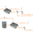
Unit 1: Fully independent ducting. Two boost switches in each bathroom with one on/off switch.
Unit 2: Simplified ducted installation. One boost switch and one on off switch.
Attached is basic diagram of my installation. Basic on other questions here, the manual and the Swidget installation, everything only needs 2-wire. (https://support.swidget.com/hc/en-us/articles/11235366697364-20-40-60-Timer-and-Auxiliary-Control-Switch-Dry-Contact-Wiring-Options)
(https://ftp.panasonic.com/ventilationfan/intellibalance/Intellibalance_en_install.pdf)
Other than for having an extra wire I can’t see the need for any 14/3 to be ran as some commenters suggested.
Am I missing anything?
GBA Detail Library
A collection of one thousand construction details organized by climate and house part


Replies
this looks wrong. you are basically trying to create a 3 way switch with your boost switches and you can't do that with 14-2. My suggestion would be this, put in a single boost switch, either next to the unit (less wire) or in one of your bathrooms. Then install a lutron cassetta switch and pair it with however many other switches you need to create your 3 way (or however many way) switch. Look up how to wire a 3 way switch and you will see this is not how it should be wired.
From your diagram you are basically creating a short in your switch....
I agree that it's odd, but it's exactly what Swidget is suggesting: https://support.swidget.com/hc/en-us/articles/11235366697364-20-40-60-Timer-and-Auxiliary-Control-Switch-Dry-Contact-Wiring-Options
I just wired my whole house so I know how to wire a three-way, but I'm following the manufactures specs.
Oh sorry, I didnt realize they were dry contact switches, that makes more sense if thats the case. Nice that they responded below!
Hi there. This is Jeremy from Swidget customer support. You can run multiple dry contact switches (S16008WA and S16009WA) in parallel to the boost terminal on that ERV, any of which being on will turn the ERV into boost mode. All will need to be off to turn off boost mode.
Each switch location requires 14/2 120V line voltage to power the switches, and a 2 wire drop to the ERV boost circuit (4 wires).
Hope this helps! Feel free to reach out to [email protected] for additional help.
Jeremy
Thanks!
Jeremy said,"You can run multiple dry contact switches (S16008WA and S16009WA) in parallel to the boost terminal on that ERV"
He said in parallel and the diagram appears to show the switches in series. I think that's where the confusion came from. Parallel seems correct, the diagram inaccurate.
Can you tell me how the Swidgets are working? I'm thinking about installing them with a Panasonic ERV as well.