Unvented roof detail with metal roofing and purlins over rigid foam
UPDATE: Look at my latest reply. My entire premise was wrong.
Hello! First post here, so please bear with me as I figure out the best way to format my text and paragraphs here.
I’m attempting to sort out some details of my future self-build. I’ve told myself if I can’t fully detail it in CAD in 3D, I’m not allowed to attempt to assemble it in person 🙂
My current focus is the roof assembly. I plan on having an unvented, conditioned attic in Zone 4C. The total roof span is 16 ft with a 15/12 pitch gable (8′ rafter span).
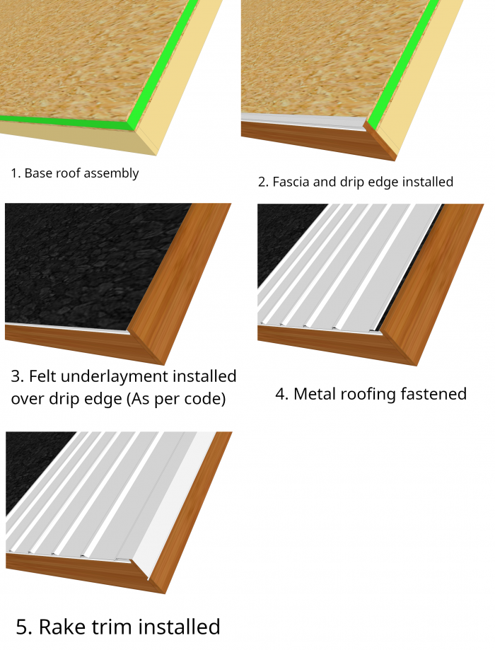
I’ve thoroughly read a few blog posts by Martin Holladay regarding this assembly and I think I have the roof assembly order mostly right:
1. Interior drywall, painted and air-sealed
2. R-35 mineral wool batts between rafters
3. Plywood sheathing, taped
4. [Optional] peel-and-stick membrane
5. 3″ rigid foam, taped
6. Felt underlayment
7. Horizontal 1×4 purlins, 24″ OC screwed through to rafters
8. Metal rib or corrugated roofing
My first attachment is what I believe the assembly would look like if I were to use a second layer of plywood instead of horizontal purlins. This detail makes more sense to me and I can visualize assembling it in my head. It seems like it would work great to direct any moisture under the roofing out and away from the house.
However, I like the purlin idea because it saves cost, weight, and labor over doing a second layer of plywood. When attempting to detail this assembly in CAD though, especially fascia and drip edges, something just rubs me the wrong way and I am a little confused.
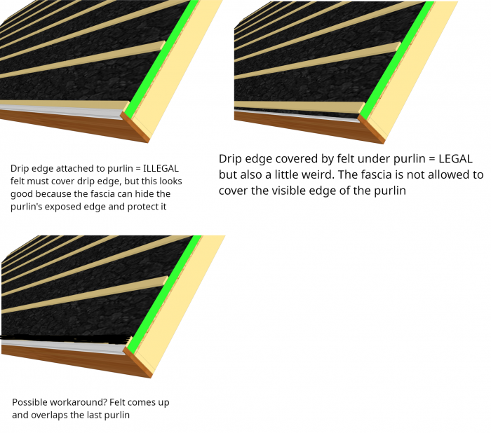
1) Where does the eave drip edge go? See my below drawing for my comments related to this question.
– If I put the drip edge on top of the purlin, this immediately violates code, but it looks nice because the fascia can cover and protect the edge of the purlin.
– If I put the drip edge under the felt (which in turn is under the purlin) this is code-compliant, but is also a bit strange as the fascia can no longer extend all the way up to cover the purlin’s edge
– What if I pulled up the felt at the last purlin and overlapped it? This seems like it’s probably wrong, because it could allow water to pool, but wanted to throw it out there.
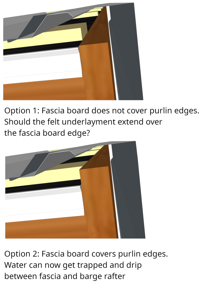
2) Does the rake/gable fascia come up to meet the purlins?
– With plywood instead of purlins, I assume the rake fascia comes up to cover the edge of the plywood to protect it.
– If we do this same detail with the purlins, does this not create a trough for water to collect in between the purlins?
– See my below drawing for the 2 options I’m thinking about
– Should the felt underlayment actually extend out over the fascia in Option 1 so that any moisture doesn’t drain into the crack between the fascia and the barge rafter?
– The more I look at Option 2, the more wrong it seems. The metal rake trim should do a good job protecting the edges of the purlins, no?
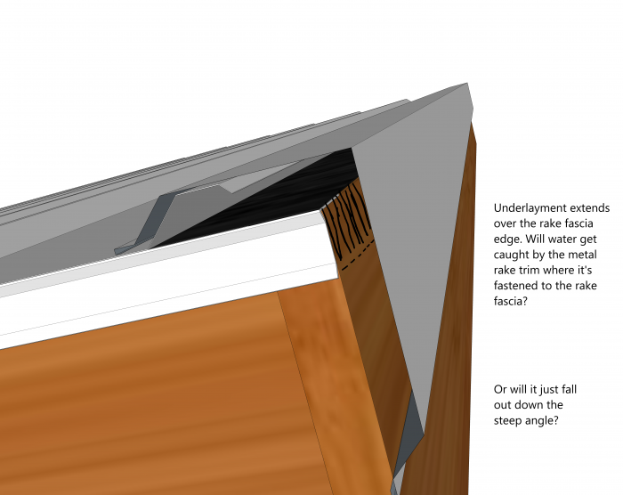
3) Should the eave drip edge extent all the way to the edge of the rake fascia instead of stopping at the end of the eave fascia board?
– I think this question is mainly a product of my ignorance. I might have detailed the fascia incorrectly and the eave fascia should actually come out and cover the end of the rake fascia, and the drip edge should be installed along the entire length of the eave fascia.
– See my final attachment below. The underlayment now extends over the rake fascia and down its face a couple inches. This detail feels more correct and robust. The drip edge goes all the way to the end.
All of the gaps with the purlins also make me nervous about bug/critter entry. I know you use foam closure strips at the base and ridge with metal roofing, but it doesn’t seem like that would take care of everything. There’s still a gap between the purlin and rake trim.
I’m probably way overthinking some of this, which I tend to do. I appreciate any advice and any corrections in my detail drawings.
GBA Detail Library
A collection of one thousand construction details organized by climate and house part


Replies
Deleted
I'll take a stab at a couple of them:
- Why not run your roof underlay over the purlins? This solves your dilemma about the drip-edge, and makes fastening both the underlay and the purlins easier and safer.
- The fascia can either come up to the top of the purlins or below them. The amount of incidental moisture that accumulates in between them should easily dissipate. To keep the edge protected, don't use the profile of rake trim you show. The gap just causes problems. Use one that lays flat against the fascia with a drip edge like this:
Unlike a shingled roof, a proper metal roof is liquid tight. This means the only water that should make it under the panels is condensation from night time cooling. I wouldn't worry too much about it unless you are pushing the slope limits which is definitely not the case with 15/12.
I recently did a metal roof with horizontal 1x4 over rigid. The underlayment went under the strapping (I would recommend and synthetic one as felt is too easy to tear), drip edge over the strapping. The metal roof panels were hammed over the drip edge.
The facia board stopped at the rigid but there was metal facia that was tucked under the drip edge. This metal facia was lapped by the underlayment, any water that does make it down, it would drain out into the gutters. The eaves troughs were also tucked under the roof drip edge.
For the rake side, I put vertical strapping along the whole edge to have a solid surface. The rake trim is close to what Malcom suggests except I used a cleat on the side for the trim to snap into so there were no exposed screws.
When complete, all the sides of the roof and rigid insulation were fully covered by metal so no chance of any critters making it in.
I would also check your local code as most places allow for compliance based on U factor. A roof with exterior insulation is much more efficient so it doesn't necessarily make financial or environmental sense to go for R49 when using expensive rigid insulation. You can simplify your life a bit by complying based on U factor which would be either an R30 or R38 assembly (~2" to 2.5" of polyiso plus R24 or R21 batts).
pcclark4 - I use same materials as you do. Plwd, P&S WRB, 2-2x4 (3") on the perimeter edge of the entire roof even with the foam to be used as a nailers for fascia bd. and all edge flashing, 2-1.5" foam with staggered seams, felt, 1x4 purlins @24" o.c.
Use the 1x4 purlins for ventilating channel. On a hip roof, I like the edge purlin over the top of the nailer to have 3"-4" spaces notched-out for ventilation, and if you have gables and shed roof, then just the side ventilation will be enough. Use insect mesh on the edges.
I have an update to this question. My entire premise was wrong. I was operating under the assumption that the IRC requires a drip edge + underlayment that covers said drip edge for all roof types. This was wrong. This requirement ONLY applies to asphalt shingle roofs. Metal roofs are exempt from this requirement. In our case, we simply do the top-left option. Instead of a "drip edge", it's usually called "eave trim" by metal roofing manufacturers.
Ultimately, you should install metal roofing according to the manufacturer's installation instructions. The IRC mostly defers to this.