

More Building Science


If a duct system is too restrictive, the blower fan will struggle to deliver enough air. Insufficient airflow can lead to poor comfort, high energy bills, and premature parts failure.
Airflow resistance can be measured using static pressures. In Part 1 of this series, we looked at the tools needed: manometer, probes, drill bit, and plugs. We identified locations in the ductwork to insert our probes. We then measured total external static pressure (TESP) between the inlet and the outlet of the furnace or air handler. TESP tells us whether the system is operating within the manufacturer’s limits.
In Part 2, we’ll use TESP to estimate system airflow. We’ll also take measurements at other test ports to examine the contributions of the return ductwork, filter, external coil, and supply ductwork to TESP. These component-by-component measurements will allow us to determine where restrictions are occurring and point us toward the appropriate fixes.
Estimating airflow
Manufacturers provide charts or tables that allow us to convert TESP measurements to estimates of airflow. The pressure/flow relationship is specific to a particular piece of equipment, mode, and setting. The table below is for a 40,000 Btu, two-stage natural gas furnace. Let’s say that the furnace is running in high-heat mode (the W2 thermostat call) and that the fan speed is set to the default (F02). If we measure a TESP of 0.30 IWC, we can see that the airflow is 841 CFM. With a TESP of 0.50 IWC, airflow drops to 752 CFM. As TESP increases and airflow falls, temperature rise across the heat exchanger goes up.
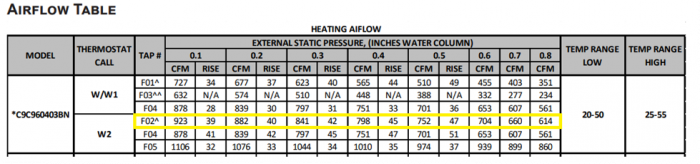
Airflow estimates can be used to fine-tune a system. If we want to save a little fan energy and deliver warmer air at the registers, we can change to a lower fan speed (tap F04). If we want more airflow…
Weekly Newsletter
Get building science and energy efficiency advice, plus special offers, in your inbox.

This article is only available to GBA Prime Members
Sign up for a free trial and get instant access to this article as well as GBA’s complete library of premium articles and construction details.
Start Free TrialAlready a member? Log in


0 Comments
Log in or become a member to post a comment.
Sign up Log in