

Image Credit: All photos: Walsh Construction Company
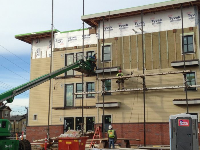
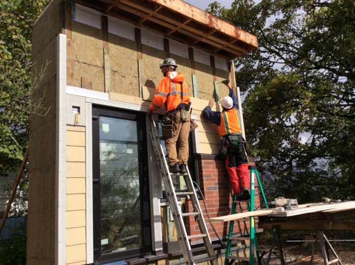
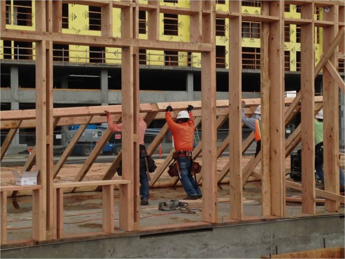
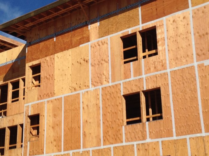
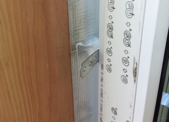
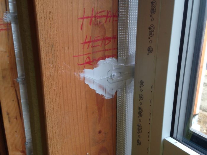
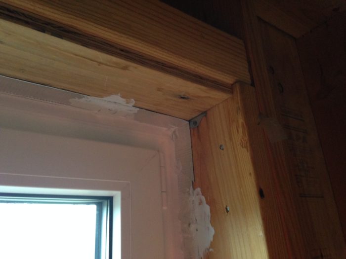
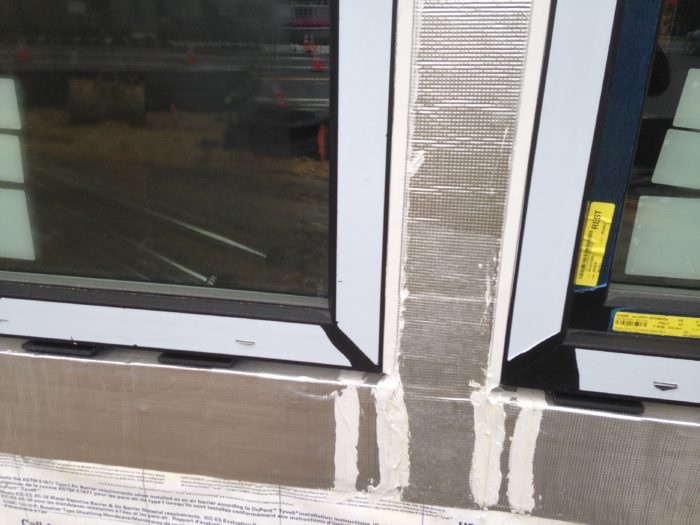
Image Credit: All photos: Walsh Construction Company We constructed a large exterior wall mockup on site and it was here that we worked out many of the loose ends of the detailing and finalized some small tweaks to the design details prior to execution on the actual building. Raising the walls at Orchards: The exterior walls are framed with 2x10s, while interior walls are framed with 2x6s and 2x4s. A view of the wall sheathing prior to preparation of the window openings. The plywood sheathing serves as the primary air barrier at the walls, so the sheathing joints were sealed with Wigluv tape. Tissi applies Wigluv air sealing tape at metal strap penetrations of the passive house enclosure. Self-adhered membrane is installed at the base of the walls, lapping onto the concrete foundation. This membrane provides air barrier continuity from the foundation to the exterior walls. The membrane also serves as a secondary base of wall flashing to ensure no water migration into the wood components of the wall. A laminate roller is used to apply pressure to the membrane to improve adhesion. High-performance windows and doors are central to the energy design concept at the Orchards project. Typical rough opening preparation prior to window installation. Strips of housewrap are installed and then peel-and-stick flexible flashing is used to wrap the openings for water management and airtightness at this crucial interface. The housewrap is held back 2 inches from the edge of the openings so that the peel-and-stick flashing can be adhered to the sheathing prior to lapping the housewrap. This provides for air barrier continuity. Note that the sill pan flashing is also being installed. The sill pan flashing is complete. Peel-and-stick flashing has been applied to the jambs. A special primer is applied to all substrate materials before the peel-and-stick flashing is adhered. A close-up of the sill pan flashing. The back leg of the pan is supported on the aluminum angle provided by the window manufacturer for attachment of the window sill. A close-up of the peel-and-stick flashing at the jamb and head of a window rough opening. The two-stage shim installed on the flashed sill of a window rough opening. This set-up allows the metal sill flashing to enter the gap between the sill pan and the window frame. Sealant is applied to the dam at the back of the sill pan prior to setting window into opening. A window is fastened at the sill using an aluminum angle provided by the window manufacturer. The angle also serves as support for the peel-and-stick sill pan. A window is fastened at the jambs and head using strap anchors provided by the window manufacturer. Sealant was applied to the strap anchor location prior to fastening. This is an important detail; encapsulating the anchor in sealant prevents air leakage. Sealant was also applied to the strap anchors after fastening. Later, backer rod and sealant were installed in the gap between the peel-and-stick flashing and the window frame. The air and water seal at the interior perimeter of a window. This seal completes the air barrier continuity from the wall to the window. The water seal at the exterior perimeter of the windows. The sill is left open to allow free drainage from the sill pan area. A cutaway view of the metal sill flashing on the mockup. The flashing is inserted into the cavity at the underside of window frame. Bond breaker tape and sealant are then applied at the gap. The flashing is placed on the lower of the two shims to provide support and maintain free drainage from the sill pan area. A piece of PVC head flashing with preformed end dams (SureSill cap flashing) is installed directly above the window frame. The housewrap above the window is later folded down to lap over the head flashing. In this photo of the exterior of a window head, the exterior mineral wool insulation, the pressure-treated plywood furring strips, and the PVC head flashing can all be seen. The mineral wool extends 1 ¼” over the window frame at the jambs to “overinsulate” the frame and improve the thermal performance of the window. The Tyvek housewrap was integrated with all of the previously installed flashings around the window and door openings to ensure proper overlaps for water management. Peel-and-stick reinforcements of the housewrap can be seen in the balcony areas where blocking will soon be installed. Treated blocks spaced 48” o.c. were installed over the housewrap at the balcony areas and where “eyebrows” (sunshades) occur. These blocks are structurally attached to the backup wall; the balcony ledgers and eyebrow framing are attached to the blocks. This allows the exterior insulation to extend nearly continuously over the wall assembly. Peel-and-stick saddle flashing is installed over each block to protect the blocks and fastener penetrations from excessive moisture. This view of a balcony area shows typical ledger blocking (at right). A sprinkler head penetration is sealed with a specialty flashing (Quickflash) that has been woven properly into the housewrap layer. The block that appears on the left is for the main beam that supports the balcony joist framing. All blocks are protected with saddle flashings fabricated on site with peel-and-stick membrane. This "eyebrow element" was framed with treated wood. The ledger is attached to intermittent blocking. The eyebrows serve to shade the windows to mitigate overheating during the summer months. One of the eyebrow elements after installation of the fiber-cement trim boards, but before the installation of metal flashing and roofing.
More Guest Blogs


This is Part 3 of a blog series describing construction of the Orchards at Orenco project in Oregon. The first installment was titled The Largest Passivhaus Building in the U.S.
An ultra-high-performance enclosure is the heart of the Passivhaus concept. The enclosure should be close to airtight and highly insulated, with limited thermal bridging.
Additionally, the enclosure should be designed to mitigate potential durability issues related to moisture. Design for moisture management is important with all construction types but becomes even more critical when wood-frame construction is used due to the moisture sensitivity of wood-based building materials.
In previous posts, I’ve addressed the context and design of the Orchards at Orenco project and the construction of the building foundation. In this post, I will describe the construction of the Orchards enclosure in more detail, while providing additional commentary on specific aspects of the design.
The Orchards team worked closely during the design phase to identify the optimal enclosure design, striving to achieve the best balance of performance, constructability, and cost. A more in-depth examination of key project details and a discussion of our collaborative process during design and construction can be found in a paper delivered earlier this year at the BEST 4 Conference: Five Not So Easy Pieces – Designing and Building the Passive House Enclosure.
We built a mockup
Construction of the Orchards enclosure was challenging in many ways, but the greatest challenges were the planning and coordination effort, given the atypical assembly designs and specifications and the relative complexity of the enclosure detailing. Heading into the construction phase, we were uncertain how tight we could get the building (58,000 square feet of floor area in three stories), so we planned a week of float into our schedule to allow for testing and remedial air-sealing work, if necessary. After completing our enclosure coordination meetings and submittal process, we constructed a large exterior wall mockup on site (see Image #2, below), and it was here that we worked out many of the loose ends of the detailing and finalized some small tweaks to the design details prior to execution on the actual building.
The exterior walls are framed with 2×10 Douglas fir studs and sheathed on the exterior with 1/2-inch plywood (see Image #3, below). To reduce thermal bridging at the walls as much as possible, we used advanced framing techniques such as 24-inch-on-center stud spacing and optimized framing around rough openings.
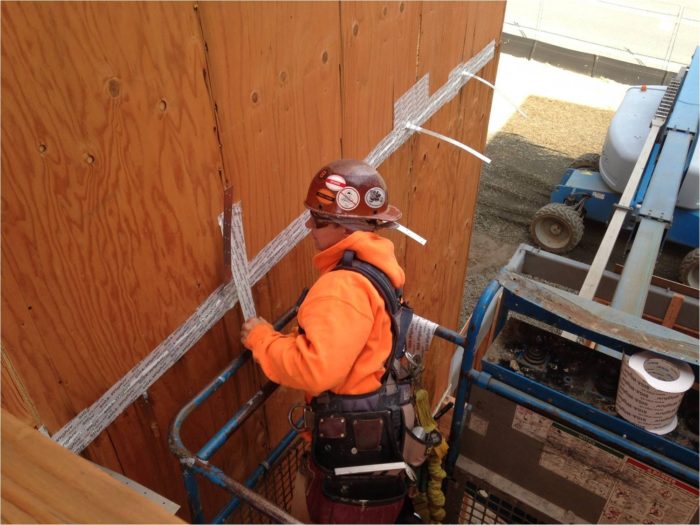
The wall sheathing is our air barrier
The plywood sheathing serves as the primary air barrier material at the exterior walls. Once the majority of the wall framing was up, our crew moved around the building, taping the sheathing joints with Siga Wigluv, a specialty tape product manufactured in Switzerland and engineered specifically for air sealing (see Image #4, below). We typically used 4-inch-wide tape for the flat seams and 6-inch-tape at the inside and outside corners. At the outside corners, the plywood often butts together roughly; we were concerned about the void behind the tape, which could lead to tears or ruptures, so we placed a small foam backer rod in those corners before applying the tape.
The Wigluv tape is vapor-permeable, adheres extremely well to the plywood substrate, and was excellent for the application. On previous projects where we’ve pursued a high level of airtightness, we’ve used a similar sealed sheathing approach; however, we’ve used wet silicone sealant at the sheathing joints and seams. Although the tape is quite expensive, the installation is much simpler and faster than the sealant method, so labor costs are reduced significantly.
Triple-glazed windows
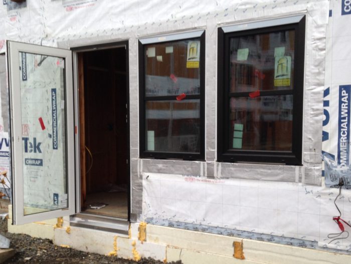
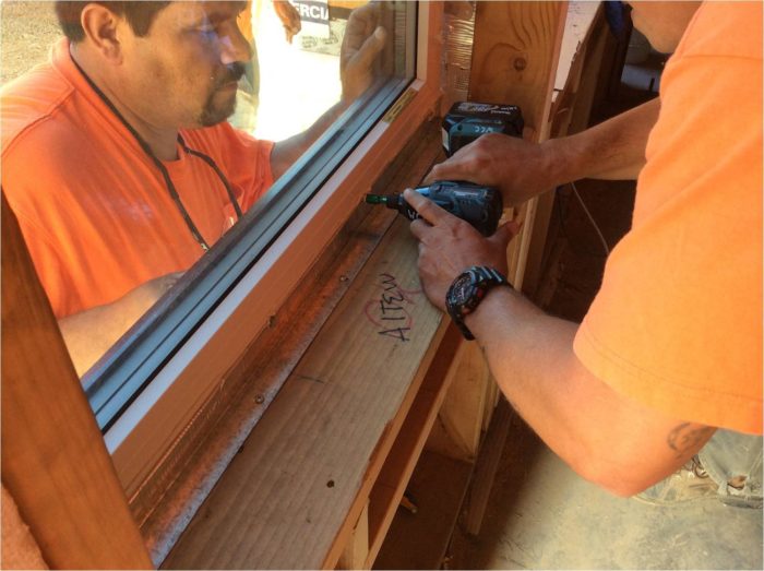
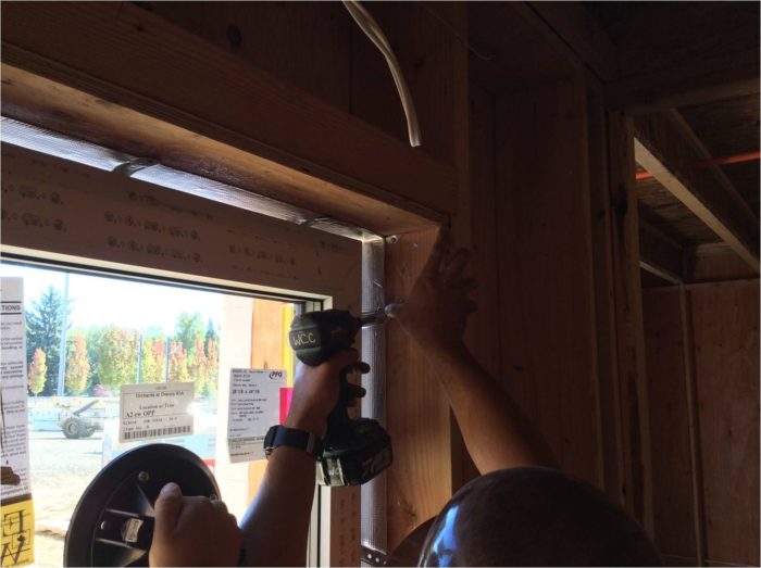
We used EuroLine 4700 Series ThermoPlus tilt-turn windows and doors, manufactured just outside of Vancouver, B.C. (see Image #7, below). These windows feature tilt-turn operation and are triple-glazed, highly airtight, and well-insulated (U-factor = 0.14). The frame material is a fiberglass-vinyl hybrid developed by Rehau, a German polymers company.
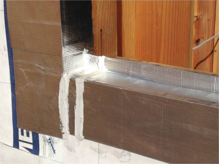
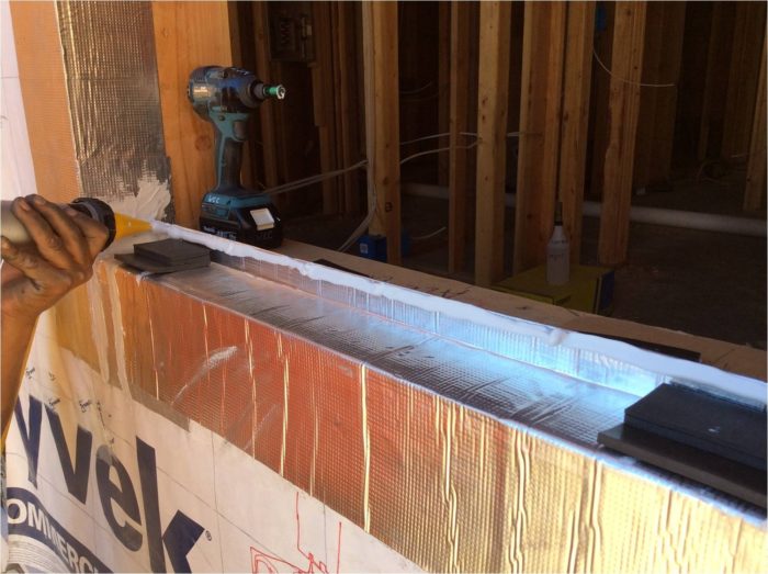
The interface between the windows and walls plays a critical role in airtightness. On many buildings, this location is where much of the air leakage occurs. To provide air-barrier continuity at the Orchards project, we installed a wet sealant between the window frame and the rough opening flashings all around the interior perimeter of the window frames.
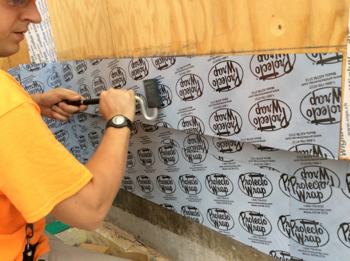
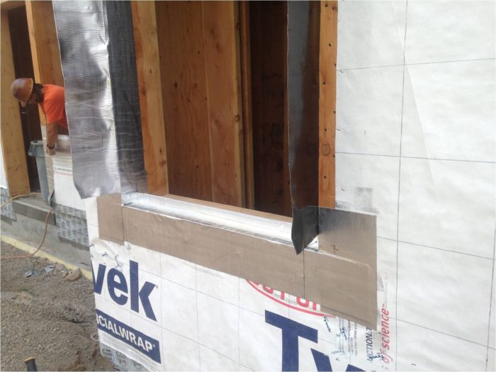
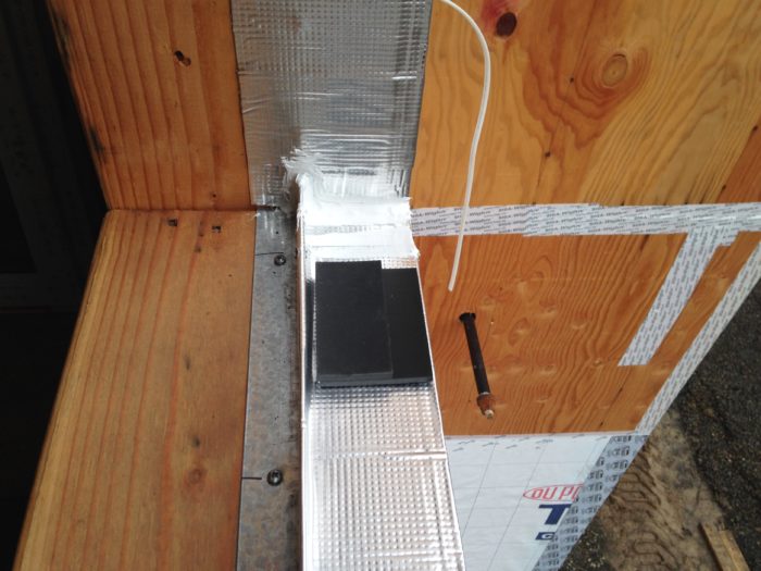
To flash the rough openings, we used a self-adhered membrane product, Protecto Seal 45 (see Image #8, below). We specified this peel-and-stick membrane because it has a foil facing that facilitates adhesion with the silicone sealant we used, Dow Corning CWS. This sealant adheres extremely well to the foil facing and also to the fiberglass-vinyl window frames.
The team agreed that it was prudent to add another seal around the exterior perimeter of the window frames at the jambs and the head to minimize the potential that exterior moisture could enter the gap between the window and the wall.
Innies, outies, or in-betweenies?
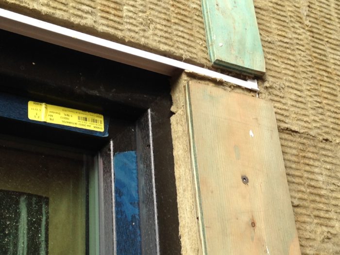
During the design phase, the team studied where best to position the windows within the wall. We considered placing the exterior face of the window frames flush with the face of the sheathing, to allow the exterior insulation layer to extend over the frames. Several iterations of the PHPP model indicated significant benefit to “overinsulating” the windows in this manner, so the team agreed with this approach.
We then encountered some constructability issues, however, especially at the interface between the window sill and the wall. With typical detailing, the face of the window frame is positioned outward an inch or two from the face of the sheathing, which allows for the metal sill flashing to be joined to the window frame outward of the sill pan flashing. This is important to maintain free drainage from the sill pan.
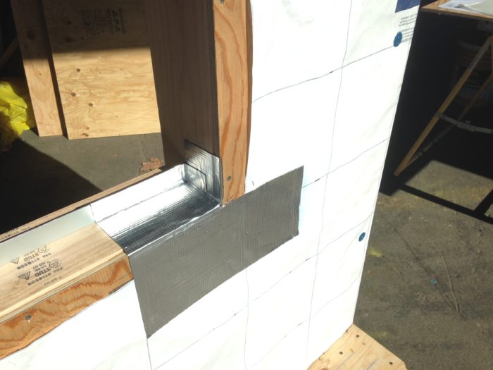
With the Orchards detail, we had to bring the horizontal leg of the metal sill flashing into the sill pan area to create the sealed joint with the window frame. To do this, we needed to shim the windows higher than is typical to provide the clearance in the sill pan area to allow for the joint but also to allow for free drainage from the sill pan. We used two stacked, stepped shims to accomplish this and it worked quite well when we installed the windows (see Image #13, below).
Delivery of the SureSill cap flashing was delayed
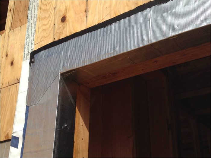
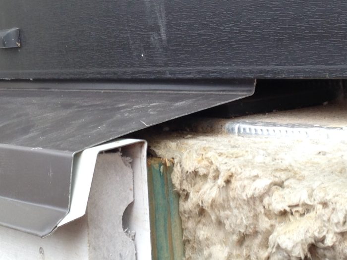
At the window head, the architect’s detail called for a rigid PVC head flashing. A specific SureSill flashing product was specified due to its three-dimensional configuration (see Figure #22, below). Typically we use brake-formed metal flashing at the window head; however, there was concern from the design team that metal flashing would cause too much thermal bridging.
The construction team thought that it would be relatively easy to source the SureSill flashing from a local supplier, and that proved true when we ordered three 48-inch-long pieces for our mockup. However, after working through the mockup, the team determined a single 10-foot long flashing piece covering both the window head and the adjacent balcony door head would work best. There was a glitch: The local supplier did not have the 10-foot lengths of flashing in stock. And then when we placed an order with the Florida-based manufacturer, we were told that they didn’t have the quantity we needed and put us on back order.
The product is actually manufactured in China and, after several communications with Florida, we learned that our flashing was literally on the slow boat to the U.S.! At that point, we were scheduled to begin installing siding in a week. Not good.
To add a little more pain to our suffering, the order got hung up for a few extra days in customs. Six weeks later the flashing arrived on site and the siding installers began their work.
Fortunately we had been able to move forward with WRB installation well ahead of the siding and got the building in the dry without delay, but the delay on the flashing delivery had some unanticipated impacts on our proposed sequencing of work.
Lesson learned: Make extra sure that thermally non-conductive flashing material is needed for your Passivhaus design before you specify it. And, if so, make sure they have adequate stock at your supply house of choice.
Testing the doors and windows for water entry
The patio/balcony doors are essentially just large tilt-turn windows, configured as doors. Exterior doors typically do not have the airtightness and water resistance to match windows, but these are not your typical doors! With three compression gaskets, the sash seals tightly to the frame, and the rainscreen design will manage water extremely well.
The owner’s representative commissioned testing of the doors and windows by an independent agency, and the doors passed field water tests up to the specified requirement of 6 psf. After passing the required level of watertightness, the test agents ran the pressure up to 12 psf and the doors still did not fail.
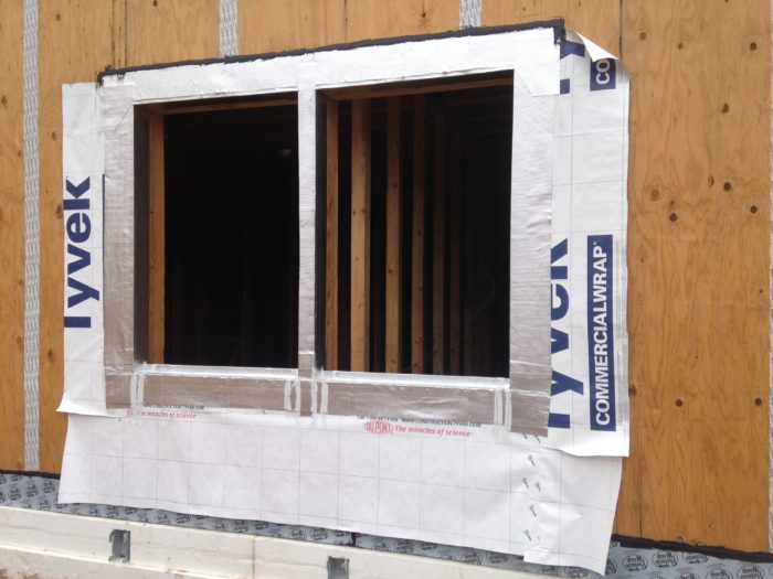
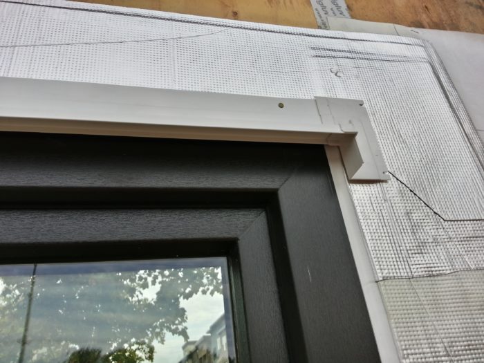
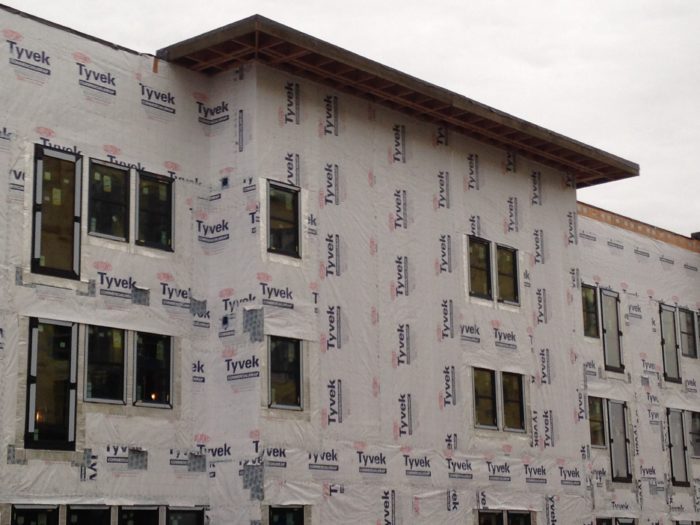
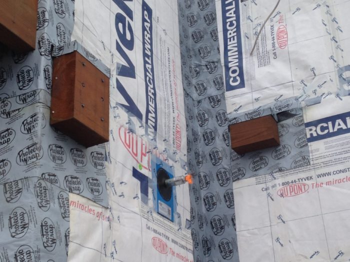
After completing the window and door installation, we installed housewrap (Tyvek CommercialWrap) over the sheathing, taking care to integrate the housewrap with the window and door flashings to ensure proper overlaps for water management (see Image #24, below).
Combined with the self-adhered membranes and various flashings, the Tyvek serves as the primary water-resistive barrier (WRB). Given the high level of airtightness and insulation in these walls, and thus the lack of drying potential, it is critically important to prevent water infiltration into the moisture-sensitive areas of the wall system.
An intensive quality control (QC) effort was essential to ensuring proper installation of the WRB and all related flashings. Nick Kurkov – one of our most highly skilled enclosure specialists – was assigned the QC role, working closely with our superintendent Jeremy Brooks, who shouldered primary responsibility for managing all of the work on site.
Balcony details
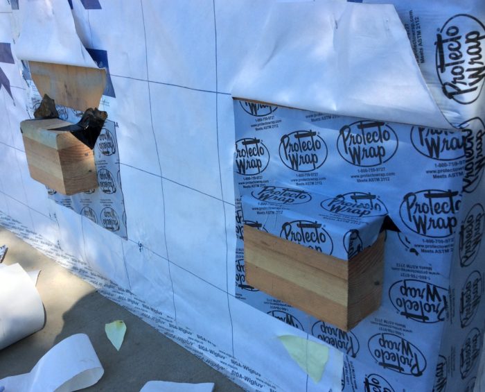
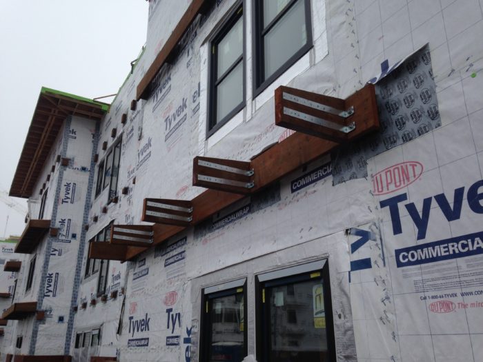
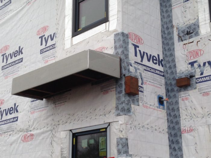
There are 36 balconies on the building, providing private outdoor living space for all residents. One of the most challenging details was how to structurally connect the balconies to the primary structure while minimizing thermal bridging and also managing water. The design solution was to provide a continuous ledger around the balcony similar to typical construction; however, the ledger is fastened to intermittent 4×8 treated wood blocking that is installed at 4’-0” spacing (see Images #25 and #27, below), so that there is a gap between the ledger and the wall sheathing.
This detail allowed us to install exterior mineral wool insulation behind the ledgers and continuously over the backup wall, thereby maintaining our thermal barrier continuity at the balcony-to-wall interface except at the block locations.
Prior to installing any balcony framing (including blocks), we installed the housewrap continuously over the walls at the balcony areas. The blocks were then installed over the housewrap and were subsequently fitted with saddle flashings that we integrated back into the housewrap. Metal through-wall flashing was then installed above the line of blocks at each balcony, allowing siding work to begin. The balcony joist framing and decking were installed last, after completion of the siding and trim.
My next blog post will address additional aspects of the construction at the Orchards at Orenco, including the roofing, cladding, and insulation.
Mike Steffen is a builder, architect, and educator committed to making better buildings. He is vice president and general manager of Walsh Construction Company in Portland, Oregon.
Weekly Newsletter
Get building science and energy efficiency advice, plus special offers, in your inbox.


7 Comments
Great article, question on drying
Thanks for a great article. Your description of the process and details was very informative and useful for me. I have a question on drying, based on this sentence: "Given the high level of airtightness and insulation in these walls, and thus the lack of drying potential...". Please tell us more about your concerns. Airtightness and high levels of insulation are usually touted as decreasing the moisture risk, although more on the side of minimizing moisture entrance and condensation. How do you see the moisture trade-off for increasing airtightness and insulation?
Response to Derek Roff
Derek,
In the old days, stud bays were uninsulated and walls were very leaky. As a result, the walls dried very quickly.
Adding insulation between studs and decreasing air leakage rates also reduces the drying rate. There are ways to mitigate the risk -- for example, by installing good flashing systems and a ventilated rainscreen gap between the siding and the WRB -- but it's still a fact that tight insulated walls dry slowly.
Thanks, Martin, but...
I appreciate your responding, Martin, but I didn't think that Mike's comment about moisture in his high-performance wall was in comparison to building practices of the 1930s. Is Mike's project, with its tight, PHIUS-grade walls, at a moisture disadvantage, compared to a similar structure built to conventional air infiltration rates and current code insulation minimums for the same location?
Great
A meticulously built project appropriately detailed for the PNW climate. I was impressed by the way it works at an urban planning level, and now that thoughtfulness appears to have carried through into the execution.
Response to Derek Roff
Derek,
Like you, I look forward to Mike's response.
But from a building science perspective, the answer is clear: the tighter the wall, and the thicker the insulation, the lower the drying potential -- and the greater the chance that any moisture that gets into the wall will be there for a very long time.
Lack of drying potential
Derek,
Martin addressed the essential issues regarding your question of drying. Adding insulation to walls reduces drying capacity because the heat flow that facilitates drying is decreased. Adding lots of insulation to walls reduces drying potential a lot. Increasing the airtightness of the walls to Passive House levels means that the potential for ventilation drying of the walls is greatly reduced. Add all these up and the drying potential has been greatly reduced compared to walls built to today's code minimum standards. And massively reduced compared to a 1930's wall.
The airtightness requirement in Passive House exists for a number of reasons but one key reason is to minimize the potential for wetting in the enclosure assemblies. My point about the WRB system (including the polyolefin sheet membrane and the flashings) is that it must be designed and constructed robustly to minimize wetting potential as well. We are protecting the moisture sensitive components of the wall assembly from wetting from both the interior and the exterior. I realize I am just repeating what Martin has noted several times already. Regrets for the repetition...
In my next blog post, I will address the materials used for exterior insulation, water-resistive barrier, exterior sheathing, and vapor barrier. All these materials were selected very specifically to increase the drying potential of our Passive House walls while also performing their other respective functions.
Need for detail
I really like the thoughtful detail reflected in this work, it's really the kind of detail that *should* be going on in all residential building. I'm currently living (because of work) in Hamburg, Germany, and there's a lot of residential building going around me in this affluent city. It's been interesting watching the work going on as these houses go up, it's been a real education. Most of the houses are close to passive (because of generally high German codes and standards), and the level of detail and quality going into these places is impressive. Germans don't work with wood in housebuilding, of course, but the same level of quality craftsmanship as seen in this Orenco house is what is expected generally. It's too bad such building is regarded as 'special' in the US...
Log in or create an account to post a comment.
Sign up Log in