
Image Credit: Image #1: Casey Braunger
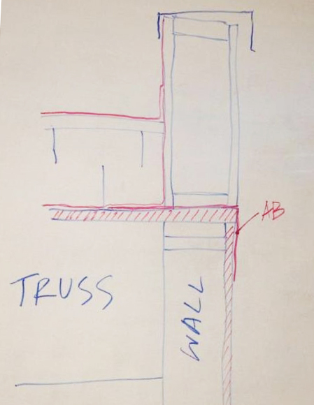
Image Credit: Image #1: Casey Braunger Concept detail developed early in design process to address need for air barrier continuity at the critical wall to roof joint.
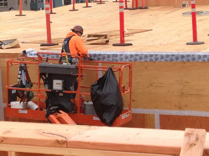
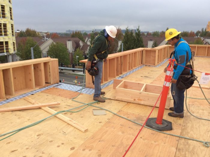
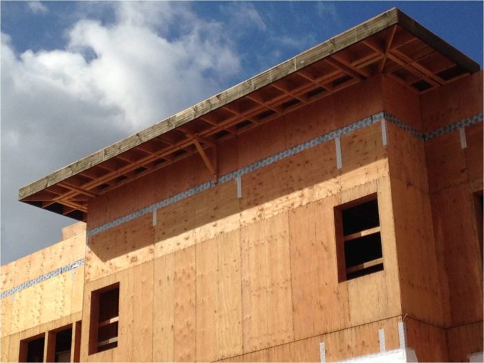
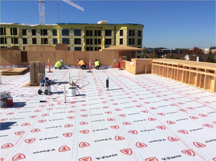
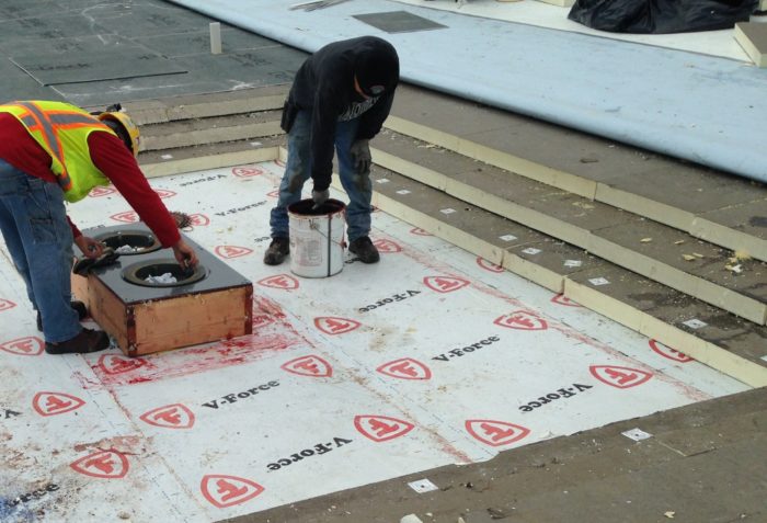
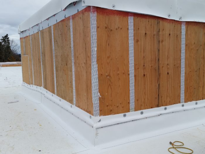
Image Credit: Images #2 through #16: Walsh Construction Company Peel-and-stick flashing is applied at the interface between the wall and roof. This essentially completes the air barrier, sealing “the box” by connecting the wall sheathing to the roof sheathing. Peel-and-stick flashing seals the transition between the walls and roof at the top of “the box.” Note the polyethylene sheeting to the right; it has been placed temporarily to keep the sheathing dry prior to installation of the membrane. The parapet wall framing was installed over the peel-and-stick flashing that was used to air seal the transition between the wall sheathing and the roof sheathing. The flexible flashing extends several inches outward from the inside face of the parapet to facilitate the tie-in with the peel-and-stick vapor barrier / air barrier that will later be installed over the roof sheathing. This photo was taken after the parapet walls were framed on top of “the box.” To complete the air barrier, the joints in the wall sheathing will be taped, the windows will be installed and sealed, and a peel-and-stick membrane will be installed over the roof sheathing. A peel-and-stick membrane was installed over the roofing; this membrane will serve as a vapor barrier and air barrier. The membrane laps over and seals to the peel-and-stick flashing that was used to seal air leaks at the transition between the wall sheathing and the roof sheathing (at the roof perimeter). The membrane also serves as temporary roofing until the roof insulation, coverboard, and TPO roofing can be installed. Peel-and-stick collars like this one were used to seal around the plumbing vent penetrations. Steel strapping and large lag screws were required to tie the parapet framing to the roof truss framing. These fastener penetrations were sealed to ensure air barrier continuity. The photo shows workers preparing a roof drain. Visible in the photo are the white peel-and-stick membrane (which acts as an air barrier and a vapor barrier), the multiple layers of insulation, the coverboard, and the roofing membrane. This photo shows the roof after the roofing membrane has been installed. The walls of the mechanical penthouse await installation of the Tyvek WRB, furring strips, and siding. The walls and roofs enclosing the three mechanical penthouses are all part of the passive house enclosure. The siding work is beginning. The photo also shows the Tyvek housewrap, exterior insulation, and vertical furring strips. Mineral wool insulation was fastened on the exterior side of the Tyvek housewrap, followed by vertical furring strips. Exterior mineral wool insulation and rainscreen furring at a balcony area. Metal through-wall flashing was installed above the intermittent wood blocking. A strip of brake-formed perforated metal is installed at the floor line just below the through-wall flashing and serves to ventilate the rainscreen cavity at the top of the siding below each balcony. The siding has been installed. Soon afterward, 2x10 continuous ledgers will be fastened to the intermittent blocking and then balcony joists and decking will be installed. Raking light shows that the painted fiber-cement lap siding is not perfectly co-planar. After some early difficulties, the siding installers were able to get the furring to lay very evenly over the continuous mineral wool insulation layer. This is the Skärbord mineral wool cutting tool. [Photo credit: Bygghouse]
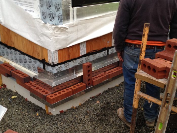
Image Credit: Image #17: Bygghouse The steel brackets at the base of the wall support the brick veneer. The brackets are installed at 3’-0” on center.
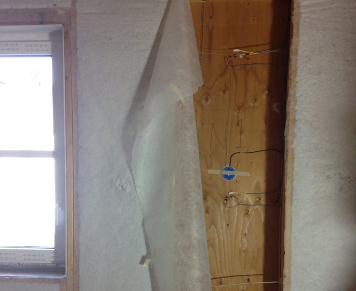
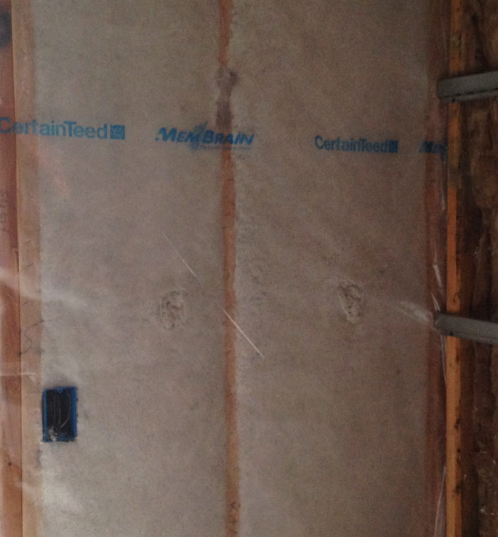
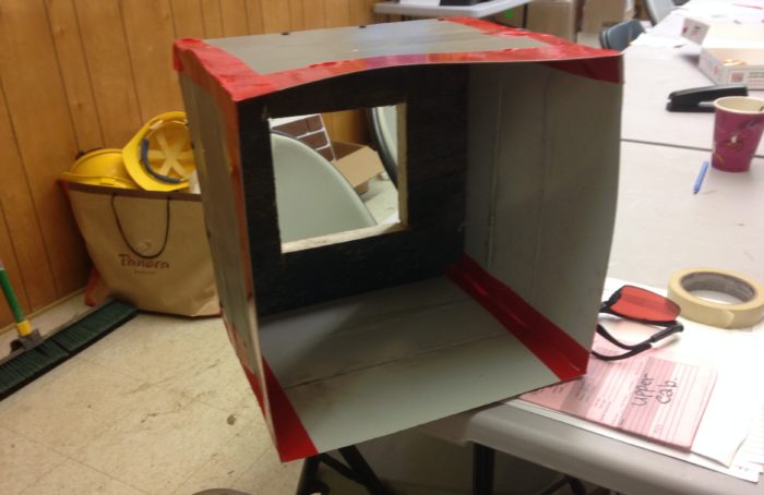
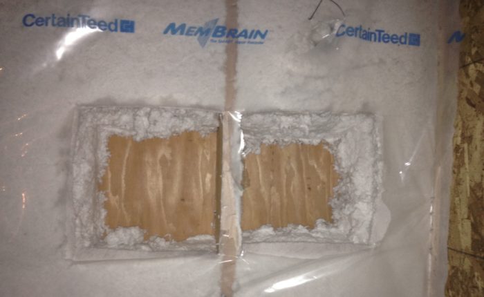
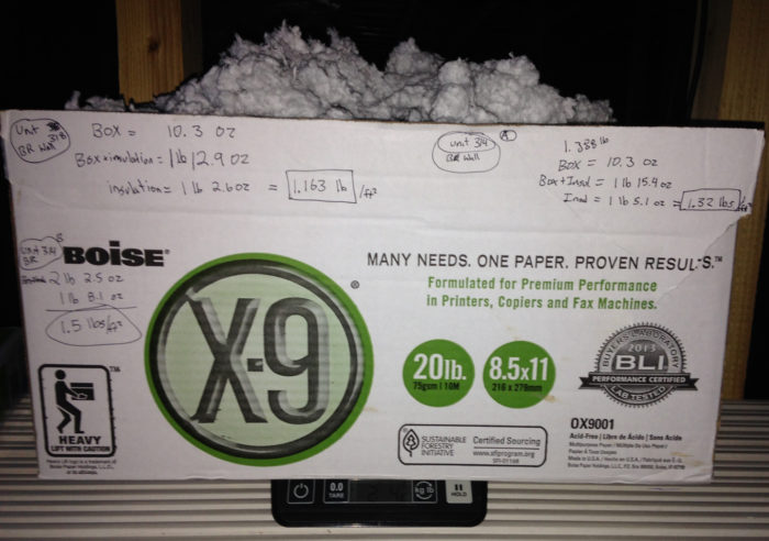
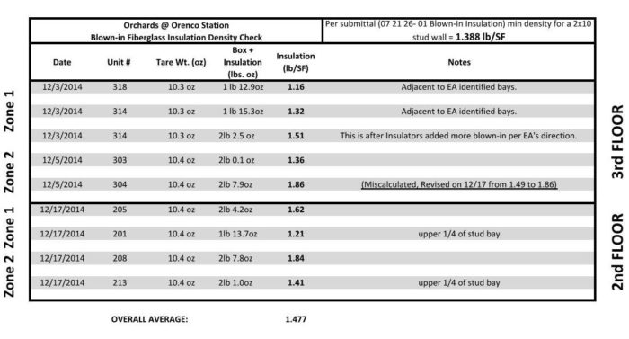
Image Credit: Images #18 through #27: Walsh Construction Company A layer of vertical EPS insulation was installed at the perimeter of the concrete foundation. The cavity at each steel bracket was filled with spray foam insulation and the excess was trimmed away. After the excess spray foam was trimmed away from the brackets, a 4x4 steel ledger angle was installed in the brackets. The steel angle will support the brick veneer. The ledger angle is covered with stainless steel base-of-wall flashing and then the brick veneer installation proceeds. Fiberglass insulation was blown into the stud cavities through netting. Here the netting has been pulled back and the insulation removed from one stud bay to allow the installation of relative humidity sensors and moisture content pins. A monitoring program – using these sensors and pins that were installed at several cavities, and in the exterior insulation layer, around the building – will provide data on the moisture and thermal performance of the exterior wall assembly. On the interior side of the insulated stud cavities, a "smart" vapor barrier (MemBrain) was installed. MemBrain has a variable vapor permeance; as relative humidity rises, its vapor permeance increases. Travis’ insulation sampling box was fabricated from sheet metal and construction tape. Insulation density test locations. A sample of insulation in a specimen box is weighed as part of the quality control process. This is the log reporting the insulation density test results.
More Guest Blogs


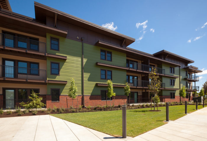
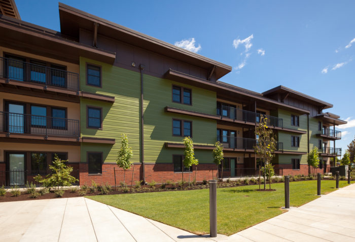
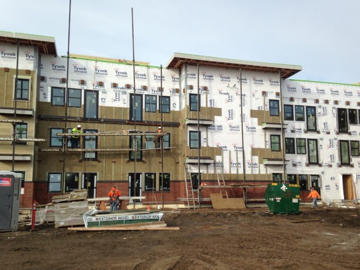
This is Part 4 of a blog series describing construction of the Orchards at Orenco project in Oregon. The first installment was titled The Largest Passivhaus Building in the U.S.
A highly insulated and airtight roof assembly tops off the Orchards at Orenco building enclosure. Overall the roof construction was very straightforward, although the parapets complicated things somewhat. Once the roof trusses were placed, they were sheathed with plywood. At the edge of the roof, we carried out a simple detail that ultimately helped us achieve a very high level of airtightness.
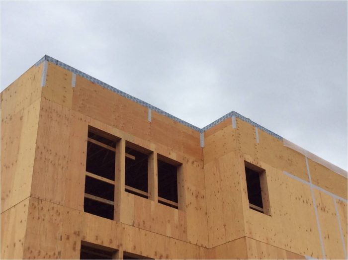
Experience on previous projects has taught us that the joint between the wall and roof is one of the most problematic areas for maintaining air barrier continuity. We therefore spent a considerable amount of time early during the design phase to discuss this issue and to develop a conceptual approach for the wall-to-roof joint (see Image #2, below). Typically, parapet walls on wood-frame buildings are framed as an extension of the roof truss framing; however, this standard approach prohibits a simple, constructable, and effective detail for transitioning air barrier from the wall sheathing to the roof sheathing.
Working with the design team, we decided that the parapet walls would be framed as separate components placed on top of the roof sheathing and fastened to the roof framing, but this would be done only after the air barrier had been transitioned from the wall to roof at the sheathing planes (see Images #3 and #4, below). The final detail followed the initial concept very closely.
Air sealing details
Once the roof framing was complete, including the parapet walls, we then installed a self-adhered rubberized asphalt membrane (Firestone V-Force) over the roof sheathing and several inches up the faces of the parapets (see Image #7). This membrane serves multiple functions: it’s a vapor barrier and air barrier for the roof assembly, but also a temporary roof to help keep the building interior dry until we could install the insulation and permanent roofing.
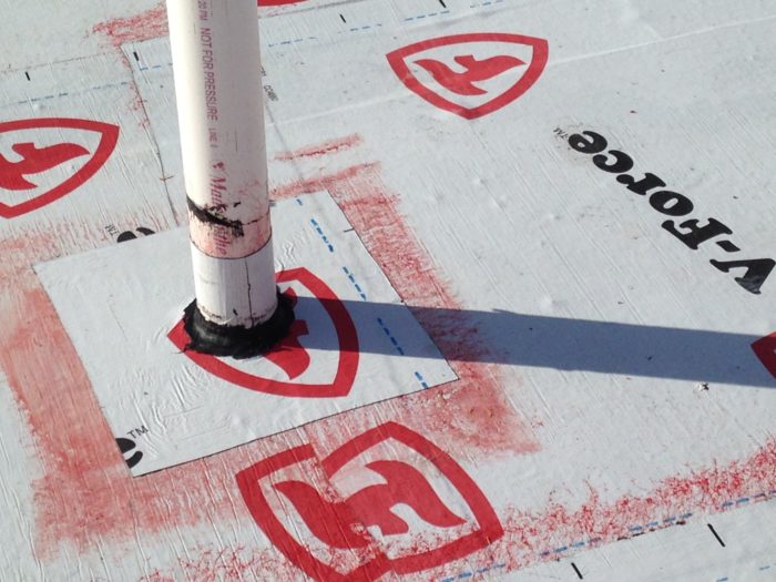
All of the service penetrations of the roof (such as plumbing vents) were sealed to the self-adhered membrane with wet sealant (see Image #8).
Exterior rigid foam insulation
Three layers of 4-inch polyisocyanurate rigid insulation were then installed over the self-adhered membrane (see Image #10). The base layer was screwed into the roof trusses and the upper layers were then adhered to each lower layer, thus minimizing the impact of thermal bridging through the fasteners.
Joints in the insulation boards were staggered to further prevent any potential thermal leakage paths. Once the insulation had been laid, a coverboard was installed and then the 80 mil single-ply roofing membrane (Firestone UltraPly TPO XR 135) was fully adhered to the coverboard (see Image #11). The total R-value of the roof assembly is R-78.
Two types of siding over exterior mineral wool
The building is clad in fiber-cement siding and brick veneer (see Image #12).
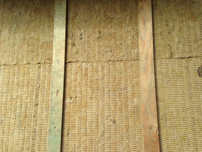
Before installing any cladding, the masons and siders first installed a 1 1/2-inch-thick layer of 8 lb. density mineral wool insulation over the water-resistive barrier (WRB), which on this project consists of Tyvek CommericalWrap. The masons used Rockboard 80 mineral wool and the siders used ComfortBoard IS mineral wool (see Image #13). Both products are manufactured by Roxul.
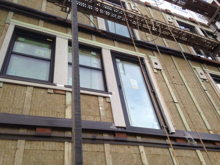
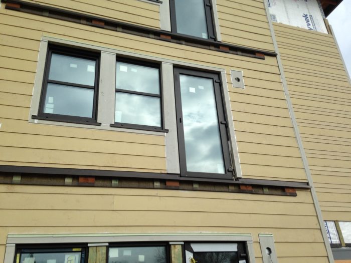
Stainless-steel masonry anchors were installed over the housewrap. These anchors penetrate the exterior insulation layer, creating minor thermal bridges. At the siding areas, ¾ inch thick x 3 inch wide treated plywood vertical furring strips were installed over the continuous insulation layer (see Image #14). The siders then nailed the fiber-cement planks to the furring strips with stainless steel siding nails (see Image #15).
The structural engineer of record for the project — Scott Nyseth of Stonewood Structural Engineers — designed the attachment of the furring strips to the backup wall: #12 hot-dipped galvanized screws, 4 ½ inches long, fastened at 16 inches on center vertically in line with the studs.
Keeping the furring strips co-planar
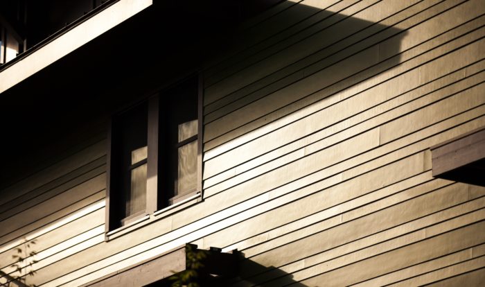
Initially the siders encountered difficulties in terms of getting the furring to lay flat on the mineral wool (see Image #16). It took some time for the crew to get a good feel for the proper amount of drive on the screws to achieve a co-planar application. On early mockups of the exterior wall, we had identified this issue, noting that plywood furring in particular was susceptible to compression into the mineral wool layer. We found that 1×4 furring when installed over the high-density mineral wool was more rigid and did not exhibit the compression problem in the same way as did the plywood furring strips. However, the siders were concerned about splitting with the 1×4 material and pushed for using the plywood instead; this was agreed to by the design team.
Roxul has issued installation guidelines and now recommends 2×3 or 2×4 furring for siding installations over semi-rigid mineral wool. Although 2x material is not necessary for structural attachment of the siding, it would certainly help with maintaining a flatter (more co-planar) application of the furring and limiting the potential for splitting.
Cutting mineral wool
Mineral wool boards can be difficult to cut to fit tightly around windows and penetrations. With a bit of research we located a tool made specifically for this application and offered it to the subcontractors.
This tool, the SkärBord insulation cutting table, is manufactured in Sweden and is sort of like a large miter box for insulation material (see Image #17). It allowed the trades to make quick, accurate cuts of the material, which helped us achieve a very high quality installation. (For more information on mineral wool cutting tables, see this GBA article: “Mineral Wool Insulation Isn’t Like Fiberglass.”)
Supporting the brick veneer
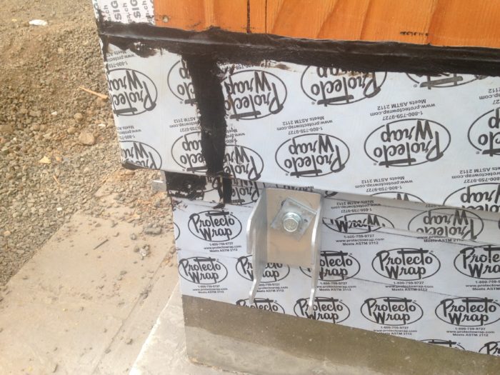
Brick veneer generally only occurs at the base of the walls, extending four feet or so up the facade. In typical construction, brick veneer is supported on a ledge that is cast into the foundation; however, this approach creates a large thermal bridge. To minimize thermal bridging at this project, the brick veneer is supported on a continuous 4”x4” galvanized steel ledger angle that has been thermally isolated from the primary structure, using off-the-shelf steel FAST brackets (manufactured by Fero Corporation), installed at 3’-0” on center along the concrete foundation around the base of the building (see Image #18).
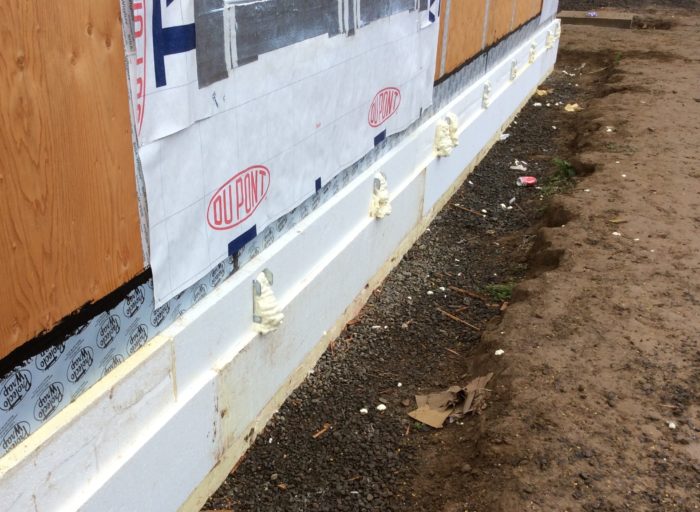
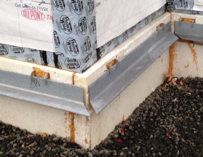
By using these brackets, we were able to apply the expanded polystyrene insulation in a continuous layer over the exterior side of the concrete foundation (see Image #19). After the steel brick ledge was attached (see Image #20), the brickwork began (see Image #21).
Blown-in fiberglass between the studs
Once the building was dried in, we began interior finish work. Insulation netting was installed over the exterior wall framing and fiberglass insulation was then blown into the 2×10 wall cavities (see Image #22). A smart vapor retarder (MemBrain) was then stapled up on the walls over the insulation netting (see Image #23).
Before the drywall was hung, the insulation was inspected by both the local building department and Earth Advantage, the PHIUS+ rater for the project. After factoring in the advanced framing methods and details, the 9 ¼ inches of blown fiberglass, and the 1 ½ inch of mineral wool exterior insulation, the total R-value of the exterior walls is 39.
An important quality control issue arose during construction: How to best verify the quality of the blown fiberglass installation in the 9 ¼” wide wall cavities? The specifications called for the insulation to be installed at a certain density; however, you can’t determine density visually. To some degree the density can be checked with a simple “mattress test,” by placing one’s hand on the netting and pushing on the installed insulation to “feel” the density, but this is a subjective assessment.
Travis Moore, our clever project engineer, developed a crude but effective measuring device to provide a more objective assessment: a sampling box constructed of sheet metal and tape that allowed for a number of random inspections of the installed density (see Image #24). The box was pushed through the netting and insulation, and then pulled back out of the wall cavity, thereby removing one cubic foot of installed insulation (see Image #25). The box was then weighed on a scale to determine the as-installed density (see Image #26). A log was developed to record the sampling done during the course of the installation (see Image #27). Through a combination of visual inspection and random sampling with Travis’ box, we identified a number of wall areas that needed additional insulation and the insulators returned to blow in more fiberglass.
Vapor-permeable materials encourage drying
Several design measures improve the moisture performance and durability of the exterior walls.
As required by the Passivhaus standard, a high level of airtightness (maximum 0.6 ach50) was specified to improve the building’s thermal performance and to limit the potential for condensation within the walls.
The wall materials were chosen with any eye to vapor permeance. This was done to maximize drying capacity: a “flow-through” design concept, if you will.
Roxul insulation was installed on the exterior to limit thermal bridging but also to help keep the temperature of the wood framing and sheathing above the dew point for nearly the entire year. A mineral wool product was specified rather than XPS or EPS due to its high vapor permeance.
The housewrap (Tyvek CommercialWrap) has a very high vapor permeance (28 perms).
Plywood sheathing was chosen rather than OSB due to its higher wet-cup perm rating (10 perms).
Lastly, the MemBrain vapor retarder was specified for the interior side of the wall — rather than polyethylene sheeting or kraft paper — in order to facilitate drying to the interior should there be any moisture remaining in the wall upon completion of construction, or should small amounts of moisture enter the wall in service.
A monitoring set-up will track moisture performance
Early on during construction, we worked with Building Science Consulting Inc. (BSCI) and Roxul to establish a program to monitor the moisture performance of the exterior walls. As the interior finish cycle began, BSCI came to the site and installed sensors, pins, and other instrumentation to serve the monitoring study.
Relative humidity (RH) sensors and moisture content pins were placed in southward-facing wall cavities at two adjacent apartments on the third floor of the building. The same application went into place at north-facing wall cavities in the two apartments across the hall. Sensors were also placed on the face of the housewrap (WRB) and within the exterior insulation layer at the same wall locations.
Sensors and pins will measure moisture content, temperature, and RH. Data collection is planned for a period of one to two years. Analysis reports, findings and conclusions will be available from Roxul at a future date.
A forthcoming blog will discuss the blower-door test at the Orchards at Orenco project.
Mike Steffen is a builder, architect, and educator committed to making better buildings. He is vice president and general manager of Walsh Construction Company in Portland, Oregon.
Weekly Newsletter
Get building science and energy efficiency advice, plus special offers, in your inbox.


![This is the Skärbord mineral wool cutting tool. [Photo credit: Bygghouse]Image Credit: Image #17: Bygghouse](https://images.greenbuildingadvisor.com/app/uploads/2018/07/24200615/Steffen%20blog%203%20-%2045.jpg)
8 Comments
Orenco, Loving the Detail
The Orenco project impresses me. Specifically,
1) The planning and detail designed to deliver energy efficiency
2) The photo documentation of the work as it proceeded. This apparently coincided with the quality control inspections that were an integral part of the construction.
3) The 'testing as you go' such as the insulation density testing.
4) The instrumentation installed to track performance during the useful life of the structure.
5) The clean and organized appearance of the work in progress.
6) The method of brick veneer mounting to minimize thermal bridging.
7) That R78 roof.
Maybe I'm easily impressed but I like what I see.
Although the overall aesthetic seems a bit humble to me, I like the window overhangs and the fiber cement siding has a professional polish except perhaps for the shade of green employed.
A project like this has the feel of engineering and execution found in a well honed manufacturing process. It's a far cry from the "materials attached to air" episode of "Construction in the Wild West" we saw in a separate recent posting. My hope for the future is restored.
the numbers please
14.5 million/57units=$254 thousand clams per 1 and 2 bedroom tiny living areas with neighbors up the wazzoo that are poor.
To me it looks like someone came up with a way to ask for free money from the free money folks to sell lots of expensive plastics tapes and sheets and so on. Complicated details.... lots of costs crazy lots of costs to do future repairs, and reroofs and painting and water damage from water getting into all the crazy layers of overly complicated plans.
Help me understand this project.
The folks are going to use public transit...ok... is the transit self sustaining? Are any public transits not subsidized? Any?
So if none of this project can be without free money added in, how is this thought of as green?
Back to the cost. To me cost has to be a factor in pointing truly to what is better. The cost of a small unit in this crowded building where no one has there own anything is $254,000. Low income buildings at the price of a new home? If the cost was $25,400 I would be raving at your success.
You missed by a factor of ten in my mind. Tell me otherwise please. I need to be educated today. Look forward to getting a better handle on multi family costs and oh the happiness of living in such a place.
The team and the overhead of "the team"
Be interesting to know how much it cost for the team?
Did the team make $2 million and a few vacations to Hawaii from this subsidized wonderful passive building?
I thought the basic energy savings of large buildings like this entailed the fact that since you have to put up with having a person with loud tv smoking on the other side of the walls that the shared walls meant energy savings since no heat is needed for the shared walls but of course there may be AC costs....
Single family homes do not need $500,000 worth of stair cases and elevators...
I just don't get the idea that cities are more green than a nice small walkable town.
Take this building and redo it with simple in mind and repair in mind, cut out the $2 million in the specialist team and drop the subsidies. Right, it's done everyday. We have a guy becoming a multi millionaire in our area doing just that.
Shaking my head still... Our schools just had their foam and rubber roofs redone. The foam all had to go. The rubber... gone... much of it looked like new... but go it did, because water may have may have touched it. Millions of dollars to redo a roof with just ONE layer of foam! Imagine the cost of redoing a roof with special overmounted parapet walls and all the details needed to build that roof!!! $$$$$ Millions folks.
Did anyone pencil up the cost of the roof redo and when it will be done? Did anyone figure the future 100 year life of this project since it is such a green project we should be thinking 500 years maybe. And?
I like the project, I bet I would like the team folks... I just am a bit skeptical of urban, green, subsidized...complicated... being the opposite of simple and sustaining.... and the numbers... $$$$ shaking my noggin at the numbing numbers...
Response to AJ's rant
AJ,
Most of the points you raise are irrelevant to the question of construction costs for a multifamily housing project in the suburbs of Portland, Oregon. Assuming that one's goal is to build a multifamily building near public transit in this neighborhood, one has to deal with the relevant construction costs as they actually are -- not with some hypothetical cost.
Presumably, the developers of this project feel confident that there will be a demand for the units once they are completed. On that basis, the project went forward.
Clearly, the construction standards achieved by the Orchards at Orenco project exceed normal standards, and should be expected to cost more than other buildings. Energy costs for this project should be unusually low.
The cost of building a single-family home in the Adirondack region of New York is irrelevant.
The fact that you prefer to live in a rural area, far from neighbors who might irritate you, is irrelevant (although it's probably a blessing for all concerned).
Your proposed cost per unit for such a building ($25,400) is a fantasy.
Cost is relevant
Simplicity is relevant.
Not needing subsidies is relevant.
Cost to reroof and maintain is relevant.
The overhead costs being far too high for a plaque is relevant.
Poor people like myself living in $300/sqft units is relevant.
I am very caring and liberal. This project spent too much to reduce energy use.
I love all that Elon Musk does and thinks. I doubt he would approve of this project's
details though he would know a better way to do such in an instant.
I agree to disagree Martin but even you who touts solar verses overly expending should see the relevance of of my points.
Comparison to ICF: insulated concrete forms
I'm curious if there was a cost analysis of the wood framing versus ICF walls. The forms are available with R-values of R50 or more.
I've visited Germany many times and they build with masonry, even single family dwellings. I understand concrete has high embodied energy, but on the other hand it's very durable.
Please do a cost analysis
My figures may be wrong.... but costs are relevant.
Another number crunch;
$14.5 million 10 year loan 3% ^ $16 million plus total cost including interest
$140,000/month 10 year mortgage payment/57 units=$2,500/month each unit. Ouch!
So the rent per month is what above the $2,500??? Rents here are $800-1,100/month for similar non green new nice units.
I love green, I do. Please go over the cost of green and the costs of projects when possible.
Costs are relevant are they not?
Please....
Aj
Costs
"Construction cost is $9.1 million on a building with 57,751 square feet of enclosed area, which figures to $158/sf. "
AJ, What difference does it make to your argument what rents are where you live? If you can build any project for 158/sf, including common areas in the Seattle area, then move there and put your shingle out. Obviously all the locals are idiots and need some help.
Log in or create an account to post a comment.
Sign up Log in