(original thread was getting long, so starting this new one focused on duct design
https://www.greenbuildingadvisor.com/question/single-minisplit-for-ac )
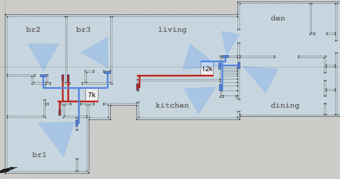
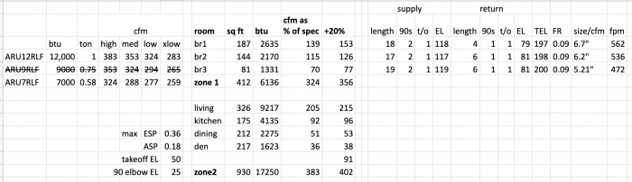
I’m planning installation of a 7+12/18k Fujitsu slim duct multisplit and I’m now at the ‘duct sizing’ stage. The Fuji 7/12 units both have a max external static pressure of 0.36 and rated blower CFM at each speed is listed in the table attached. Units will be mounted in an unfinished basement with ducts run through closets/floors/stairwell. Proposed layout is below and I’ve been using a copy of Manual D and and ductcalc.ca to size things. Would love any general feedback, and then help with some specific questions:
1) Should I size ducting based on maximum blower cfm? Then on lower speed I just get lower cfm, lower velocity, less throw from register, etc?
2) I understand high/low supply/return register placement is kind of a toss up depending on whether you’re cooling/heating dominant. Ceiling is not under consideration as I want to keep things in conditioned space/basement. I’m leaning towards high supply because I’m worried about furniture obstructing floor supplies. For high sidewall supply registers, what is the target throw distance relative to room size?
3) For returns, I’m planning individual returns for each bedroom and then one central one for the ‘living area’ zone given how open that space is. What should my target be… supply cfm +x% where x = 10%? 25%? 50%?
4) Here is a collection of slim duct manifolds I’ve found photos of:
https://bit.ly/2XYFsPh . Apart from the one with three round outlets, I’ve not seen any for sale online. Do people just make these in the field? Just guess at EL based on the most similar fittings in Appendix 3?
5) Manual D Appendix 3, sections A2 and A3-3 state all the provided EL numbers are based on 900fpm/0.08 FR and must be adjusted accordingly. Correcting to 600 fpm drops the EL by 50%+, which would then impact the friction rate, which changes required duct size, which would then change fpm… etc. On top of that, all the registers have different pressure loss at various fpm. Do I actually have to find the intersection of all these variables? Or do I figure out a combo that works on paper within blower spec, install, measure actual static pressure, and then adjust down blower to match?


Replies
I'm not enough of a duct designer answer most of your questions, but...
For the low-static versions, shoot for duct velocities of no more than 400-450 feet per minute, which keeps the static pressures low even in imperfectly implemented ducts. It's fine to taper down for higher velocity at the registers. Mike MacFarland's nomographs of cfm to fps against duct sizing in this blog work pretty well, but his target velocities are more geared toward more powerful air handlers. You'd be working on the left third of the nomograph when using low-static mini-splits:
https://www.greenbuildingadvisor.com/article/the-best-velocity-for-moving-air-through-ducts-part-2
https://www.dropbox.com/s/pwgwl5m8vryqh5c/Duct%20Sizing%20Using%20FPM%20Targets%20and%20CFM%20MacFarland.pdf?dl=0
Consider using an oversized pleated filter on the return side to keep the filter's static pressure low even when filtering to MERV 10 or higher. The low air velocity through an oversized filter improves the filtering action, as well as keeping the static pressures down. (An Aprilaire 2400 isn't insane here, even though it's more commonly used with 1000 cfm+ air handlers.)
Thanks, I had not seen that chart or article before... makes me feel better about what are looking like significantly lower velocity numbers than the 900 mentioned in Manual D.
1) Should I size ducting based on maximum blower cfm?
Yes. I also like to ensure there is at least 15% margin on pressure for buildup on the filter. You don't need all your ducts to have the same pressure, but need to have a way of balancing them.
2) I understand high/low supply/return register placement
Stay away from return registers in the floor, these are garbage magnets. It is always best to have a filter right at the return register. Well sealed filter and return ducts means very little dust getting into your system, no need to ever clean it.
For supply registers, take a look at the room layout. You generally don't want to blow air across people sitting or sleeping. If you have no choice, try to reduce the velocity down to around 150 fpm.
3) For returns,
Don't plan on leaky ducts, return flow is the same as supply flow rate.
4) Here is a collection of slim duct manifolds I’ve found photos of:
You want your plenum to look like either Untitled image or f8b46dc675cb8c209d706291c9858161.jpg.
The rest are pretty lossy for a low static pressure unit.
The easiest is to get a shop to make you a plenum that goes from the opening of the ducted unit to either a flat or faceted face. On this you install standard takeoffs to feed each room.
On the return best to get a transition that tapers from a standard duct size (ie 8x24) to the opening on the cassette. Use swept bend for all return piping.
5) Manual D Appendix 3,
I only check the the most convoluted duct, and yes that needs iteration if you want to get exact numbers. Or you can just take the EL at the higher friction rate and call it a day.
No matter what, you need to install balancing dampers and set the air flows when you commission the system. Once you set the air flows, check your static pressure and configure the mini split accordingly (usually an install parameter on the thermostat).
Also don't forget to add in the register boot EL to your pressure calcs. Some configurations are very lossy.
Very helpful, thanks for all that.
I have been struggling to come up with a way to get returns up high in the bedrooms' zone. 1957 plaster walls so no desire to cut holes any holes other than for registers. I want the supplies up high so as not to impede furniture. My plan is closet chases but not much room for that in BR3, and even less in BR2. Maybe with some creativity I can at least get them on the wall at floor height so skittles don't fall in.
For the BR zone I really like the layout afforded by having the supply and return trunks parallel, but blowing directly into a T seems inherently bad for airflow. Is it more important to get smooth transitions on the supply side, at the expense of a less direct return layout?
Typically 50's houses have plaster over drywall lath, these are a bit easier to work with as they are smoother on the inside. From the basement, just cut through the bottom plate between the two studs and install the duct up to the register opening. Not too messy. I doubt you need more then a 10x3 1/4 duct for a return on a bedroom anyways and that easly fits inside the wall.
You can pretty much do what you want with the plenum as long as the pressure loss is fine. T shape is not the greatest but if you make it large enough, it doesn't matter. Adding in a V shaped flow splitter in the middle of the T would not hurt. I think two side elbows would be much cleaner and less restrictive though. Sharp bends are restrictive, doesn't matter if on supply and return side.
Don't forget to add in space for a filter on the return before it gets to the bedroom cassette.
Looking at your floor pan again, it looks like you have no supply to the den. That is a big room with two outside walls, it should get its own supply.
Yes you are correct, walls are plaster over blue drywall lath boards. Wall stacks sound like a good plan, I should be able to do that and well worth the effort to get the returns up off the floor. I actually have photos from the original house construction and don't see any blocking in the interior walls, so hopefully that's the case.
I will come up with something creative for the supply plenum.
No easy way I can see to get supply to the den so I was going to skip it, put those BTUs into the dining room and hope it at least mixes somewhat. The opening between the two is ~5' wide. The wall on the right is actually to an unheated garage, so maybe a little better than exterior wall. The dining/den was an addition so there's a block wall separating the crawlspace under that part from the basement in the rest of the house.
For the return filter I see cfm/2 as a common guide for sq in of filter space, so ~400 cfm would be 200 sq in or 20x10. This is bigger than the return duct I planned on using... do I just tilt the filter on an angle? Or enlarge the duct to accommodate? Also sounds like the 4"-5" thick filters offer higher surface area and less pressure loss, but I would not really be able to angle one of those. Any recommendations on common filter size to target would be great.
Slim duct units do much less head than a furnace, that rule of thumb won't work.
You generally want at most 0.1" across the filter, so for typicall filter ratings that comes to 150fpm, so your 400cfm would be looking at a 16x25 filter.
Bigger is always better. Generally try to put in the largest filter you can, thicker is better if you can fit it. Just make sure you have room to slide it out.
Tilted filters work quite well. Easiest install is right behind a larger return grill like this:
https://uploads.disquscdn.com/images/2ffa6e108a7ded9f51130ff14126239b275b1244b7d53138beb63b4182d68f13.jpg
For your bedrooms, it might be simpler to go with door undercuts or transfer ducts for each room and a single return in the hallway.
I would try to get a duct to the den. You can always add in baseboards for supplementary heat, but that feels wrong after doing all this work.
Deep pleats will increase surface area more than tilting a flat filter. Use a rule of thumb only if you can't calculate the actual pressure drop.
Re 5' open doorway: at 1623 btu/hr load in the den, at design temps it should be < 3F delta from the other rooms (usually less).
What is the purpose of the long red duct on the 12K unit (vs locating it quite close to the air handler)? My understanding is that with open doorways, return location doesn't matter - it's register throw that determines mixing and when that is correct, diffusion within a room happens without any assistance from return location.
https://www.nrel.gov/docs/fy12osti/53352.pdf
There's an existing wall register there that opens directly into the basement. The previous owner had installed it to get hot air up from the wood stove that used to down there. I plan to enlarge it and then run the return ducting back to the 12k. Seems like the extra 10' of straight duct run has a negligible effect on Total Effective Length and friction/pressure/sizing calcs. Those are just openings (no doors) between the all the rooms in that 12k zone so I am hoping one appropriately sized central return will suffice.
#4
I found a UK supplier of molded Plenums - they match up with the various US models. They ship to US
https://www.airconplenums.com/fujitsu-plenum/arxb-07-18-galh/arxb-07-18-galh/fujitsu-arxb12-18galh-supply-air-plenum/
Those model numbers don't match up to US model numbers though do they? Which one corresponds to Fujitsu's RLFCD series?
Those are very lossy plenums, a sharp takeoff is around 35' EL, whereas a tapered one is 15'. With a low static head, you are better with getting a sheet metal shop make you a simple box plenum and use standard tapered takeoffs.
I shot them a note looking to see if they fit with an ARU9RLF or ARU12RLF. Below is the response.
"Yes they do. In Europe Fujitsu use different reference numbers for their products. In this case the model is ARYG07-14LLT. The plenum boxes to suit this unit can be found here:
http://www.airconplenums.com/fujitsu-plenum/aryg-07-18-llt/aryg-07-14-llt-a-and-b/
Akos may be right on the added length -- I have pretty short runs to the immediate room where the unit is locates and to two adjacent bedrooms. Though I might see about raising the takeoff with a fabricated box (still wrapping things up). I decided to fabricate my own return. Includes a 10x20 right off the side access combined with an 8" round to 12x12 in an adjacent room. Rigid duct. I like the ability to position the unit vertically.
I'll take a few shots and add shortly.
Thanks for this post, it answers a ton of questions for me! I have a few more of course...
I'm planning using a 9RLFCD as well for heating three bedrooms upstairs (total gut and remodel). Haven't purchased anything yet. Manual J gave my total load upstairs as 12,851 BTU's, and from what I understand it's better to slightly undersize the unit. Given the rated heating capacity is -5˚, and the heating design temperature in my region (SE CT) is 0˚, I think I should be OK. Yes...?
My duct design challenge is a straight supply duct that runs in a partition between two adjacent rooms (BR 3 has the unit in the closet, so it's just an elbow out of the plenum). Because it's a non load-bearing wall, I'm considering hiding the duct directly on top of the plate of the partition and just making the wall a tad thicker. (I'll probably scab plywood on either side of the duct for support). This duct will be in the conditioned space, in other words. 4x11 run edgewise, probably. I'll cut openings in the duct to feed each bedroom.
Does anyone happen to know the EL of a rectangular opening in a duct (no boot)? I don't have Manual D, could someone point me to a chart somewhere (or at least, which publication I ought to purchase and from whom)? My Size-A-Duct slide rule thingie has a chart for hard 90˚'s, is that what I should use? Because my duct run is short, I'm sure my FR will be plenty low, so maybe I shouldn't worry? Still I'd like to know.
How do I approach the issue of balancing dampers? In this case, would the register itself function as a damper?
What is the relationship between duct size and register size? Are they equal? Like, if the CFM requirements for a room dictate a 4x11 duct, is this the size the register ought to be (or two equivalent smaller ones, perhaps, depending on the shape of the room)?
>"Given the rated heating capacity is -5˚, and the heating design temperature in my region (SE CT) is 0˚, I think I should be OK."
The -5F is the lowest temperature at which there is a specified capacity, not the " ...rated heating capacity...". The specified maximum capacity of the 9RLFCD@ -5F is 13,500 BTU/hr.
That is NOT the net output factoring in defrost cycles, but the maximum it can deliver at that temp. There will be some derating for defrost, but it'll be good for at least 12.5- 13K-net@ -5F in anything but rime-icing fog conditions (which would be pretty rare at -5F in CT, even if it's somewhat common at the summit of Mt. Washington in NH.)
The "rated" or "nominal" capacity is the modulation level at which it was tested for efficiency at +17F & +47F with the inverter locked to 60Hz under an AHRI test protocol, which is 12,000 BTU/hr per the submittal sheet.
>" ...and the heating design temperature in my region (SE CT) is 0˚,"
Not so! Even the 99.6 th percentile temperature bin in your area is in positive digits. For most reasonably tight homes with at least some insulation in the walls it's customary to use the 99th percentile temperature bin, which for most of SE CT would be between +5F and +10F (warmer for coastal towns.) For instance, the 99% outside design temp for Norwich is +7F, New London's & Norwalk's are +9F:
https://articles.extension.org/sites/default/files/7.%20Outdoor_Design_Conditions_508.pdf
https://www.energystar.gov/ia/partners/bldrs_lenders_raters/downloads/County%20Level%20Design%20Temperature%20Reference%20Guide%20-%202015-06-24.pdf
https://www.captiveaire.com/catalogcontent/fans/sup_mpu/doc/winter_summer_design_temps_us.pdf
Using +5F for the design temp would be more reasonable than 0F, or even +10F for coastal communities.
Under the manufacturer's testing conditions the max capacity at +5F is 15,000 BTU/hr, which is 25% above your ~12,000 BTU/hr heat load at +5F. That is sufficient margin for most cold snaps, but it wouldn't be crazy to bump it up to the 12RLFCD, which can deliver 16,500 BTU/hr @ +5F, about 1.35-1.4x oversizing:
https://ashp.neep.org/#!/product/25312
https://ashp.neep.org/#!/product/25310
ASHRAE recommends a 1.4x oversize factor for the load at the 99% outside design temp, and if I were confident in the heat load calculation I'd personally be specifying the 12RLFCD in this case (YMMV). The minimum modulation levels are the same for either, and the COP @ 47F (closer to your average heating season load) is a bit higher at the low modulation end @ 47F for the 12RLFCD than the 9RLFCD too.
> it's better to slightly undersize the unit.
For heating, it best to oversize the max system output (including supplemental heat and output greater than rated/nominal output) by about 25% to account for temperatures that will be colder than the design temperature.
Be sure to account for the velocity (eg, 700 fpm) needed for proper register throw.
So, a smaller register just means a higher throw, to a point? Probably that point being, enough movement to mix the air but not so much that things get breezy in there... and keeping the static pressure within bounds as well. Is there such a thing as too low a static pressure?
Would the balancing damper be a part of the register itself, if there's no boot? Each register is just an opening in the duct, covered by a grille (I've seen many of these in commercial systems). Or, does there need to be a boot so I can stick a damper in it?
> Would the balancing damper be a part of the register itself
A damper in the duct makes no use of the pressure drop (ie, wastes energy). The same restriction as part of the grill could increase throw and mixing.
One technique to prevent airflow from creating discomfort is to shoot the airflow across the ceiling.
Cutting a hole in a rectangular duct to feed a room works well if there is a fair bit of pressure behind it. With a mini split, you probably won't have enough, if the pressure gets low enough, you can start to suck in air from the room through a cutout like that.
To get it to work, you'll need to form a scoop into the flow. You can probably get close enough by making the cutout like flap attached on the downstream side of the duct, then bending this flap into the duct to create a scoop. You can adjust the amount of flow coming to the register by how much the scoop sticks in.
The one issue with a single duct like you are looking to use is sound. You'll get a lot of transfer between the rooms. If you have room, it is always better to run individual ducts. If you don't have the space get some duct liner (rigid insulation panels with facing) into the duct on the face opposite the registers.
I can run individual ducts, quieter is better and it sounds like the zoning will work better too.
Upstairs I'd like to run flat oval. Is the EL higher for equivalently-sized flat oval bends than for round? I'm guessing hard vs. easy flat oval bends are different. Does the Manual D handbook have an EL list for flat oval fittings? (I'm not sure I need to spend $80 on the manual, but maybe I do... ) I found a useful instruction manual for duct design which has EL lengths listed at the end... but only for round and rectangular ducts:
https://www.cedengineering.com/userfiles/How%20to%20Size%20and%20Design%20Ducts.pdf
Good info on ways with dealing with oval in walls, has EL for most configurations.
http://eccomfg.com/pdf/News/OVAL%20FITTING%20STUDY_rev3.pdf
You're awesome! Thanks!
http://genewoltz.com/HTML/NOBA/Assets/Library/ANSI-ACCA_Documentation/ACCA%20Manual%20D.pdf
You must have some awesome internet search skills to find that!
It's a gift. Thank you!
You can see in Figure 1-11 on p.5 (p25 in PDF pagination) why I was recommending 400-450 feet per minute as an upper bound on duct velocity when using low static ducted mini-split cassettes. While that graph is looking only at the pressure drop at the coil, it also applies in proportion to ducts, filters etc. At 450 fpm the pressure drop is about 1/3 of what it would be at 900 fpm across the same coil (or duct, or filter...), and at 300 fpm it's less than 1/3.
Bigger air handlers typically have the cfm flows rated at 0.8-1.0" w.c, whereas low-static Fujitsu xxRLFCs can meet the flow specs at no more than 0.5" w.c., and Mitsubishi KDxx only 0.2" .
Okay got this thing up and running, will post some pics when I catch my breath.
One question... install manual says to measure external static pressure and then configure the blower accordingly by changing a setting to the appropriate iWC.
I got myself a digital manometer and some probes. Do I stick them into the supply and return, immediately before and after the unit(s)? Also plan to do before/after filter to see what the drop over 12x24x2" NordicAire MERV 12 is.
The number you need to program in is the differential pressure across the cassette, so probe before and after the unit.
Balance the bedroom flows before setting this though, balancing the flow tends to add a fair bit of pressure.
I did not balance anything, other than trying to size the duct work according to cfm required. I don't know how, don't have a hood and most importantly, didn't have time. Did I mention I was doing this install during a 2 week trip back to NJ to work on the house? Total install time was 10-11 days. This was my first HVAC project and I had a helper for about half that time. Overall things went largely according to plan and I am pleased with how it turned out. House is cool and comfortable, and the system is surprisingly quiet, both the inside units and the compressor.
I was able to run returns high with wallstacks up in the walls for 2/3 bedrooms, the third was via 8x8 duct in closet chase. All three returns were right in a line so I was able to tie them into a single 12x8 return duct which transitioned down via 24x12 shortway elbow followed by 24x12 broadway elbow. Short section of 24x12 straight duct into which I cut a filter rack for a 12x24x2 filter (.07 measured drop). Then I cut and bent the 24x12 to a flange to meet the return opening on the cassette.
For the 7k supply I made plenum beginning with a short section of 24x8 duct fabricated into a transition that mated with the 25 1/2 x 6 supply flange. From there I used three square-to-round funnel boxes, 8x8x8/7/6 and riveted them together, leaving a 1" flange around the outside which I slide into s-lock on the 24x8. Riveted it all together and applied a healthy serving of mastic on all the seams. 8/6/7" round ducts to the bedrooms via closet chases. Measured static pressure across the 7k cassette was 0.22.
For the 12k supply I started with ~2' of 24x8 (one end cut to mate with the supply flange) and then transitioning down to 16x8. Shortway bend up the stairwall wall followed by a 16x8 offset I fabricated. Another short section of 16x8 followed by another funnel box manifold thingy, this time branching into two 8x8x8s. Each of these was followed by an easy flow tee, 8x8x6 feeding the two living room ducts and 8x6x6 branching off to the kitchen and dining rooms.
Return was a 16x25 wall mount grille with 1" filter. Deeper would have been nice but I didn't have the space. As it was I had to notch ~3/4"x25" out of a stud to make it fit. This went into a 16x25x16 return air box I made hidden in a kitchen cabinet. The bottom opened to the floor joist below, so 16x14 1/2. I cut and bent some 3x4 sheets of 30 gauge steel to line the inside of the joist cavity, overlapping the seams and sealing with mastic. This ran ~4' horizontally then dropped into a 16x8, transition back to 24x8 and then to the cassette. Measured static pressure across this unit was 0.25.
Compressor mounted on an aluminum wall bracket and the two runs were 30' and 40'. I had an HVAC buddy pressure test the lines with nitrogen and then pull vac via micrometer. Drain lines were 3/4 in PVC.
Total cost was ~$6500: $3000 for the units, ~$1500 for duct work, $1000 for labor (helper and commissioning) and the remainder in miscellaneous stuff and a few sheet metal hand tools.
Some pics are below. Thanks to all who offered their input and advice.
Hey there Jeffesonm,
Just wondering if you could give me an update on how your system is performing. Still happy?
What are your thoughts on mounting the outdoor unit on the wall of the house, any issues? Noise level ok?
How did the commissioning/TurningItOnForTheFirstTime part of the install? Did you use the manometer?
Is there a wired controller/thermostat for these, and if so, where did you mount it? Was it hard to program the thing?
Thanks again for the useful information, I'm about to purchase three of these. Wish me luck!
Yes so far so good... happy with the performance, noise, etc. Time will tell on reliability and longevity.
Originally I'd planned to mount the outdoor unit on the end of the house more out of the way, but right along the backyard wall made for an easier install. No worries on the noise, it's super quiet even at startup. Nothing like my parents traditional AC. Air handlers are very quiet too... all you hear is the gently woosh of air, no fan noise.
For the commissioning bit I had an HVAC guy (friend) purge the lines with nitrogen, pull a vacuum and then release the refrigerant. I borrowed a flare tool and did the flares myself, which did not leak.
Turning it on was anticlimactic. There is actually relatively little in the manual about first time startup procedures, it's more like 'install it correctly and turn it on'. It does say to wait 12 hours after charging the lines before operating the compressor... not sure why, but I did. Then I ran it in fan only mode for a bit, just because, but then it was game on.
I did use the manometer to measure static pressure and then set the air handlers accordingly. It was like $30 from amazon and $15? for 2 probes.
Yes wired thermostats... for the bedroom zone I put in on the wall in the master (where I care most about the right temperature) and for the living zone it's on the wall in the living room. In both cases about chest height and not directly in the output of a vent. No programming required really unless you want to do setbacks or something.
Overall the ducting took longer and was more complicated than the actual units, but even that was because I fabbed a bunch of stuff myself, jammed returns up in finished wall cavities, etc.
>"Yes wired thermostats... for the bedroom zone I put in on the wall in the master (where I care most about the right temperature) and for the living zone it's on the wall in the living room. "
My understanding is that the controls for the xxRLFs are wired REMOTES, not exactly thermostats. Even though the remote has a temperature sensor, the default mode is to sense the temperature of the air entering the air handler for controlling the modulation level rather than sensing at the remote, unless programmed to use the sensor in the remote instead, which makes it behave like a thermostat.
I haven't looked up the particulars on that in the manual, but it's a good idea to figure that out before the first cold snap or you may see some pretty big temperature offsets creeping in. I'm pretty sure it is related to the ECONOMY /Thermo Sensor button on the lower right hand of the panel or not, the function of which isn't well explained in the manuals I've scanned. You may get more out of these videos than I did:
https://www.youtube.com/watch?v=NZw3k8PvMeY
Scroll forward to the 1:30 tick on this video:
https://www.youtube.com/watch?v=OhT8pEHpjfg
I wish I had an HVAC friend! Good thing I have you guys.
It's going to take a while before I'm actually ready to turn on my stuff (especially since it hasn't arrived yet) but if I run into any serious problems I may pester you again.
Thank you again everyone for all the useful information. You've been very generous and it is truly appreciated.
Hey, I've got a good question for someone. I came across this duct product which is called Cobre29, which happens to be semi-rigid copper duct. I also saw a similarly made semi-rigid aluminum duct at the Home Depot that had me wondering. Do people use this stuff for ductwork? Seems like a good middle ground between flex and rigid (definition of, rather). You would presumably have the advantage of being able to snake the stuff all over the place without having to do a lot of "tin knocking" while also not having the disadvantage of the usual flex duct, which is that it gets pinched and not pulled tight, etc.
I would assume the corrugations would increase the friction of semi-rigid over smooth rigid duct of the same size, but perhaps I am wrong?
Cobre29's product literature points out that there are fewer fittings which makes it less leaky, also you can do gradual bends with it which help reduce static pressure, over a series of 45 or 90 degree bends or whatever.
So ok, let's say everything is great and the stuff is great. How do you calculate the friction rate of a duct with a gradual bend in it? Is there a chart somewhere with equivalent lengths for various radii??
Oh yeah, and the stuff is available in flat oval. Just to make it interesting. Ok, so the only place I found is in the UK. I did however see an episode of This Old House in which a guy installed a flexible chimney liner, which he had squashed into a flat oval shape himself to fit into a rectangular flue. It looked good. The sort of thing one could accomplish with patience and skill.
This is the stuff you are talking about: https://www.homedepot.com/s/semirigid?NCNI-5
It can work and but will have more friction. Just keep the velocities low and be conservative on the friction loss estimates.
See tab G8 for the relative friction for different curve radi and angles: https://www.acca.org/communities/community-home/librarydocuments/viewdocument?DocumentKey=040c19f6-d77e-45b1-b484-111cafb25cf1
or Appendix 3 in manual J
You can approximate the curve you are making and use the fittings as a reference.
I would generally only use semi rigid in select places where you are pulling duct through a space that requires curves, but you can't get into to air seal after things are in place. It makes sense mostly for short sections.
If you really want to calculate the losses, I think this is a proper reference: http://www.mcgillairflow.com/assets/literature/ductSysDesign_guide.pdf
See page 248 "Flexible duct, Metalic". It looks similar to flex.
Manual D has a flexible metalic duct loss chart: See page 154
http://genewoltz.com/HTML/NOBA/Assets/Library/ANSI-ACCA_Documentation/ACCA%20Manual%20D.pdf
Hey Jeffesonm,
If you're still there. Where the heck did you get those awesome square to round transitions? None of the local supply houses have seen anything like it. I may be stuck having to modify a register boot. Did someone make those for you?
Any particular reason you went with rivets? The FW Webb guy sold me sheet metal screws, but I've worked with rivets before too and they seem like a good thing, not so pointy when you stick your hand in a duct at any rate...
They are Gray Metal Products series 318 funnel boots. I purchased them locally from Dasco, an HVAC/sheet metal supplier in Edison NJ. I had also found them online here: https://abrwholesalers.com/brands/gray-metal?e_series=318
All the rest of the ducting was attached with sheet metal screws, I did rivets on the manifolds because they're super secure, permanent and less pointy on the inside. In truth, I'm sometimes just irrationally perfectionist.
I think you and I are similar thinkers. Thank you so much once again!
"funnel boot" is not a term I was likely to come up with left to my own devices.
There's a Dasco in Stamford, and I'm on my way through there on Wednesday this week so I can stop and pick up some parts.
As usual, your advice is invaluable.
jeffesonm: > Correcting to 600 fpm drops the EL by 50%+
I don't have Manual D, so can you talk about this more? EL is a ratio and so shouldn't change much when going from 900 fpm to 600 fpm. See below, where a similar change in flow rate only changed EL from 26 to 24 (an 8% drop). Would also be interesting to see a discussion of how balancing changes with flow rate (and lots of other things). Seems like maintaining tight temperature control is all rooms is impossible without zoning.
https://www.gohvacsales.com/static_docs/tech_tips/10_the_difference_between_equivalent_length_and_effective_length.pdf
Disclaimer: I'm not a mechanical engineer, or someone versed in fluid dynamics, or anything like that... just a DIY guy who reads a lot.
Here is some draft/review copy of Manual D which I think is good enough for our purposes: http://genewoltz.com/HTML/NOBA/Assets/Library/ANSI-ACCA_Documentation/ACCA%20Manual%20D.pdf
Consider Figure A3-2 - Equivalent Length Versus Velocity for 0.08 IWC/100Ft Friction Rate
Slowing the air from 900 fpm to 600 fpm drops the Equivalent Length figures by 50%+.
My layman interpretation of this is... when you're trying to move the air real fast, going around a tight bend really slows it down. If your air is not in such a rush, the impact is less, and if your air is taking it's sweet ass time, it hardly matters how many bends there are.
That link you posted seems to reference changes in air flow (CFM) vs air speed (FPM) so perhaps the former has less of an impact on Equivalent Length than the latter?
From Manual D:
"The equivalent length value (ELx) for another velocity (Vx), and/or another friction rate (FRx), is calculated by this equation:
ELx = EL X (Vx/Vr)² x (FRr/FRx)
For example, a default equivalent length value is for 900 Fpm air velocity and a 0.08 friction rate, and the Section N4 equivalent length value is 65 feet; so the equivalent length for 700 Fpm and a 0.12 friction rate is 26 feet.
Elx = 65 x (700/900)² x (0.08/0.12) = 26 feet
Thanks for the Manual D link. The Appendix 3 chart and example is wildly misleading since it holds friction rate constant (or little drop) when it typically drops exponentially.
The formula is correct: ELx = EL x (Vx / Vr)² x (FRr / FRx)
Let's use the example 900 fpm, the default EL of 65 ft and dropping to 700 fpm. At these velocities, a 12x12" 100' duct will have roughly (from another calculator):
FRr = .105 (inches wc/100')
FRx = .066 (inches wc/100')
So we have:
65 * (700/900)^2 * (0.105/.066) = 62.56 = ELx
So with reasonable numbers, the EL dropped about 4%, from 65 to 62.56, not the big change that some think. On the other hand, 4% could result in a significant 3F difference in temperature (say between two very differently ducted rooms that were balanced at low air flows).
Summary, EL changes some with velocity - but usually single digit %.
Equivalent length and friction rate are just "design tools" used within manual D. The manual D approach generally produces a duct system that will work, but it is not good for doing something like predicting static in a system. I think it falls short when you want to figure out something like designing a short run with limited space and making that work with the rest of the system.
I am not an HVAC pro. I am a mechanical engineer though. For detailed work, I get away from talking about equivalent length and work in pressure drop. I find it more informative to work through the full Ashrae calculations, but it is more work. You can learn how here:
http://www.mcgillairflow.com/assets/literature/ductSysDesign_guide.pdf
http://ftp.demec.ufpr.br/disciplinas/TM184/VENTILACAO_LOCAL_EXAUSTORA/DUCT_DESIGN.pdf
ASHRAE has an app that limits the need to work through tables to find loss coefficients, I think it is $10.
Jon, EL is just a comparison of pressure drop through a fitting relative to a straight duct of a certain length. That relationship does not change much with velocity, as shown by your equation. What does change is the pressure drop through the fitting.
65ft *.105 (in)/100ft = .068"
62.56 * .066 (in)/100ft = .041"
It's easier to work in pressure. Use the original 65ft *.105 (in)/100ft = .068"
.068" (700^2/900^2) = .041"
I can't contribute anything to the above math stuff, instead I have more questions as usual.
My understanding thus far is that it's ok to use the "standard" EL values for fittings and such. Because these values are taken at the higher velocities generated by "normal" air handlers, the only downside to using these numbers is that the actual friction rate will actually be a bit lower than the calculations suggest, due to the slower velocities generated by low static pressure units such as the Fujitsu RLFCD's I'm working with, and this is a good thing. It's also ok to oversize the ducts somewhat to slow the velocity further as this will further lower the static pressure. The fan will not have to work as hard to push the air. My calculations gave me a duct size of 3 1/2" in two instances, so I've scaled this up to 4" since I have no idea where to get 3 1/2" duct. This is ok, right??
Another question I have is about "throw". So far what I've learned is that constricting the exit point using a diffuser with angled blades results in a higher velocity as the air exits the duct, which blows the air through the room and distributes the heat better. Not sure how to calculate the ratio between duct size and diffuser size. My only thought is to simply use the biggest diffuser boot I can get for that size duct (for example, a 4" round can go to a 4" x 12" register).
Is this a good approach?
But I'm wondering just how important "throw" is when discussing a very open floor plan. Specifically I'm trying to figure out the duct layout for my 18RLFCD indoor unit, which is hopefully heating my Great Room and Mudroom. The whole first floor is very open but the Great Room has a really high ceiling. There is a soffit at the transition which I've decorated with a weathered barn beam. My original design called for an 8" round duct to heat the Great Room, and my plan was simply to expose it and call it beautiful.
In the drawing you can see where I am planning on hanging the 18K unit (on the ceiling in the Mudroom) and hiding the duct along the top of some cubby-style mudroom cabinetry (I'm a cabinetmaker by trade). I was going to continue this duct by exposing it, across the ceiling and hang it from my exposed decorative weathered beam (indicated by the dotted line on the drawing) and just stick a round egg-crate style diffuser at the end of it. But maybe I don't need this additional 7' of ugly duct and I can just stick a diffuser at the end of my cabinets (the end of the arrow in the drawing)? Will the heat just even out by natural convection? I will give the Mudroom its own 4" duct regardless, so I know that will get heated. Mostly wondering about getting the Great Room comfortable.
Maybe my proposed duct run is actually way too short and I should continue my duct along the entire length of the Great Room and put a series of diffusers spaced every 8' or so, like in the attached photo? To distribute the heat better... and I would have to increase the size of the duct in this scenario to lower the static pressure...??
You have to be careful with exposed ductwork. It only looks right in loft style places, looks out of place in the picture you attached.
Cooling your great room is most likely possible with a long throw register(high pressure drop) by the mud room, heating it comfortably definitely not.
Even the best windows create a cold air down wash which tends to settle at ground level, you need some way of mixing up this air otherwise the place will never be comfortable. No point in designing an energy efficient house if you have to wear slippers all the time.
Your options are to get enough air flow and mixing at all areas of the room, in case of your layout would mean running ductwork all the way to the end of the room with a set of diffusers you can adjust to blow downward in the winter and horizontally in the summer.
The other possibility is to add in some supplemental heat near the windows. Either a small panel heater or a narrow strip of resistance floor heat bellow. These don't have to be lot of BTU, just enough to mix up the air flow a bit and reverse the convective loop from the windows. The mini split would still do most of the heating.
Overall, it might be simpler to just find a spot for a wall mount in the center of the room and use the kitchen ducted unit for heating the mudroom.
Using manual D excel speedsheets as is or just constant velocity is fine for these systems if you have dampers installed. Rounding up in duct size is the way to go.
Your heating loads look high, what is your design temp and how did you calculate the loads? What is the construction? You have 36.5Kbtu of capacity spec'd at 5F, which is a lot for the amount of space I see, particularly if there is a floor above (are those stairs in the drawing?)
EDIT: Thinking about your 4" duct too. You can only get 35cfm down a 4" duct at 400FPM. Thats only 1.24kBtu/hr from an 18RLFD.
An on your distribution question, you choose the diffuser base on the throw, CFM, and pressure drop you can work with, then choose the boot that matches the diffuser.
All about distribution:
https://www.priceindustries.com/content/uploads/assets/literature/engineering-guides/air-distribution-engineering-guide.pdf
Example data to choose diffusers:
http://www.hartandcooley.com/files/assets/files/1363456373_C%20Series.pdf
Basic rule is don't blow air directly on people. The importance on throw is largely dependent on the quality of your windows and where people will sit relative to them. Minisplits reduce the need for good distribution because the run most of the time.
Some say that register throw and location (as long as it is in the room) are no longer important with low load homes. But I've yet to see good data supporting that claim. Windows can still create uncomfortable drafts, stratification still occurs.
Based on reviewing some numbers, I believe that balance will typically shift around and will cause excessive temperature variations. So consider zoning - for example, thermostatically controlled dampers that produce a 0-20% reduction in flow rate (going completely closed causes side effects).
Thanks guys!
I did my Manual J using coolcalc.com which is a free online tool. You can choose to manually input things like construction details, room size, orientation, number of appliances, adjacent conditioned spaces, orientation, etc., but the program can also pull information from Zillow. Of course I entered everything manually, except for the design temps which the program provided automatically. I'm in Mystic, CT and I think 5 is our low temp but I could be mistaken.
My house is from 1840- I didn't provide any scale on the drawing but the total square footage is 2300. I think I'm doing pretty good insulating and air sealing, but I'll not be doing anywhere near as well as you all with new houses. I think this is why my heat load may seem high.
After trying several local contractors and paying one guy $500 for a load calc, that guy turned out to be using coolcalc (beta) and his numbers were totally wonky- the larger, less well insulated great room with more windows in it, had a much lower btu load than the kitchen. I thought it was hogwash so I googled coolcalc and found I could do it myself. I got way different numbers and a much lower total load.
About my 4" duct, I was pretty sure I did the math right, but perhaps not? I based my CFM on the number of CFM produced by the unit at the high fan speed, and multiplying this by the percentage of the total load of each room. In other words, if you add all the CFM's of the rooms together you get the total CFM of the unit heating those rooms. Maybe this is where I went wrong? For the rest, I used the instructions provided here: https://www.greenbuildingadvisor.com/question/horizontal-ducted-minisplit-ducting
There is also a formula on my Duct-o-lator cardboard slide rule thing, that amounts to the same thing. When I used it to size my ducts it told me the mudroom needed a 4" duct and the Great Room needed an 8" duct; seems appropriate given their relative sizes, but then, perhaps both of these ducts are way undersized?? So I missed something in my understanding of the formula.
Between my living room and kitchen I have a 12K unit that hides in a closet and is mounted vertically. There are two extremely short ducts, each with a single 90˚ bend, blowing in opposite directions. I confess I am tempted to simply divide the supply opening on the unit according to the load percentages and make two rectangular ducts using the resulting sizes (one at 6x10 and one at 6x16, or somewhere in that neighborhood. The supply end of the unit is 6x25 5/8"). Super bad idea?
I was also planning on buying diffusers that have dampers in them so they can be opened and closed. I've seen ones (Keen home I think is one brand) that do this automatically but I figured this system might end up fighting with the minisplit; perhaps they are actually a good idea?
Yeah something's off with those duct sizes. Assuming 560 CFM from the 18RLFCD (I think that's about correct) and your mudroom being 25% of the load for that unit, you'd have about 140 cfm going there. At 400 fpm that needs an 8" duct.
To get a 3.5" duct result you'd have to have a friction rate over 2 (the 18RLFCD can only do 0.36 before any filter/damper/grille deductions) and a velocity of over 2000 fpm, so something has gone awry there. Try punching the numbers into here and see what you get:
http://ductcalc.ca/
You can go by friction rate or velocity to see the sizing for various CFMs.
Conceptually, there is a lot to be said for something like "Flair Smart Vents". Basically a thermostat and automatically adjusted damper in every room, but smart enough not to cause problems with too low airflow.
With very short, simple runs, small duct sizes are correct in terms of pressure drop. If you up-size to reduce velocity, then you have to restrict the flow elsewhere (eg, damper or diffuser).
Double check your design temp, I am seeing 14F for New London, CT
http://ashrae-meteo.info/places.php?continent=North%20America
The place is bigger than I thought based on a guess at the size. I was thinking the floor plan you showed was 1000-1500sf. You can always post a thread on your manual J.
Coolcalc is okay, but I found occasionally has some catastrophic bugs, mostly related to infiltration /ventilation. So check the those numbers.
I think your duct velocities are a high, even if the static actually work out. You think you risk noise unless you really know what you are doing. Dampers at the diffusers can be add to this noise.
Automated dampers are a pretty advanced option to get right on a minisplit at this point. Your issue seems like it will be more about Getting sufficient mixing and distribution much more so than zone control.
Regarding your load calcs, if your entire duct system is located within the conditioned space, did you select "ductless" on the HVAC System page of coolcalc? I am asking because I recently started using coolcalc to calculate the loads for a ducted mini-split system which will be located completely within the conditioned space. I knew there was a problem when there were losses from the ducts. I sent a message to support and this was their response,
"The program will still give you the CFM breakdown by room on the last page of the report. The correct way to handle ductwork that is 100% in the conditioned space is to not add ductwork at all. Even if we had a location option for "conditioned space" the result would be neutral since all of the losses and gains would end up back in the conditioned space."
I still think that they should add the option because it's not intuitive to select "ductless" when designing a ducted system.
The other issue with coolcalc that I've seen mentioned on GBA is that it overestimates loads and in particular, the infiltration loads may be overestimated. I chose "average" but I don't really know the definition of "average." This is one of the other problems with coolcalc- there are no definitions. I'm still trying to figure out what to measure for "slab edge," since it's also not defined. Without definitions and/or instructions, errors can be made because it's garbage in, garbage out.
Jeffesonm, I hope you took advantage of the NJ Warm Advantage program where they give a $2000 rebate for every high efficiency ducted mini split unit (per outdoor condenser). Check to see see if your units qualify. I am not sure the multi head ducted units are efficient enough, but I know the single head ducted Fujitsu's are. ). I think you can apply after the fact but not sure of all the qualifications . Check it out by searching for "NJ WarmAdvantage".
In CT the rebate is only good if an approved contractor does the work. Booo.
Matt, you're read of the scale is probably about right, since 2300 includes the square footage upstairs. I'll go back and recheck my coolcalc about that design temp. I will say we did see -7˚F last December, but 14˚ is certainly more normal in these parts.
I didn't notice an HVAC section in my Coolcalc but maybe I just didn't look for one. It's a free account so maybe that's it? I'm using the instructions provided by many kind folks here to the best of my ability. I'm glad to be rechecking this stuff with your oversight!
Ok so here's my math example. The 18K unit has 554 CFM (Mr. Levinson you were right on). Based on the loads, I get 141.75 CFM for the mudroom and 412.24 for the Great Room. Because I hear it's good to oversize ducts I increased these numbers by 20%, which gives me 170 and 494.7 respectively.
For the mudroom I'll need a thing to go from rectangular to round (a "takeoff" or "funnel boot" or some such). Jeffersonm gave an EL of 10 for this item. I'll need a 90˚ elbow, manual D says these are valued at 20'. I gave myself another 6' of straight duct (I think I'll reduce this because I changed the location of the unit from the wall to the ceiling). Anyway I get an EL of 36.
I'm using an Available Static Pressure number of .31 to account for the pressure drop of the return plenum and external filter and the supply diffuser as well. Harte and Cooley lists their 12x4 sidewall diffuser with a drop of .062" at 175CFM. I went with this size because it's the first size I encounter on the chart at that CFM number.
I need to recheck the return filter because I had to buy what they store had available, it's this: https://electronicaircleaners.com/255649-102.aspx
The specs for the Trion Air Bear don't list the pressure drop below 600 CFM: http://docs.electronicaircleaners.com/trion_airbear_specification.pdf
But the smallest value they list is .o5 at 600CFM.
.36 is the ASP of the unit, sooo....
.36-.065 - .05 = .248.
.248÷36 x 100 = .69 which is my friction rate. So when I use my Coleman Size A Duct I get a duct size of 4 3/4". So really, I should scale my duct up to 5".
Did I do it right?
I was planning on boofing up the size of my return plenum so that the filter is basically the only loss on the return end. Maybe this isn't possible?
Using only pressure, I get the same numbers as you. But you should also calculate velocity (effecting noise), which will cause you to go larger. Like 6" and 11".
> I'm using an Available Static Pressure number of .31
Going lower (say < .2) will be quieter, save energy and provide more error margin.
NJ seems to say the same thing on the web site but I called the people handling the rebates and they said they would accept a self install. Time will tell for me when I try it......but I suggest you give a call to see if they would make an exception in CT, particularly since you have done more calculations than most pros do!!! Can’t hurt.
Hi Jon!
As you can see I just edited my reply...
Anyway, I'm thinking of redesigning the mudroom/great room duct because I'm putting the unit on the ceiling instead of the wall. There's actually a powder room in the corner (not shown on the drawing) which can have a lowered ceiling to hide the unit (with an access panel of course). I'm lowering the walls of the powder room to allow air to circulate freely with the rest of the space. Could be a great way to distribute stink through my whole house! The supply duct can hide along the top of the mudroom cubbies, it will just be straight.
I can easily make a rectangular duct in any size. I got myself some Kingspan Koolduct board which is phenolic insulation board faced on both sides with foil, they say the friction is the same as metal duct and the R value is 10. I can chop it up on my tablesaw and glue it and tape it so it's strong and tight. Somewhere along this trunk I can cut a hole to heat the mudroom, and then the end of the trunk can just end where the cabinetry does, pointing at my great room.
But, maybe the mudroom should have its own 5" round duct as originally designed, and I should hide a 8" round duct on top of my cabinets? Should this duct continue onwards for the whole length of the great room? There's no good place to hide it, keeping it as low as possible in the room is still about 7' up. I'd rather not have to look at a duct, but of course we do need heat and stuff. I wonder how much 30' of spiral copper costs... Otherwise I guess I'll just paint it black and hang christmas lights on it...
Best to run a 11" duct to the far end of the room. Even better if directs warm air towards the cool air pouring off the windows. How much these things matter is unclear.
Plan on using a dehumidifier for Summer AC. The CFM/ton is way off at anything less than full load.
The only sad thing is I got the ducted unit so I wouldn't have to look at it... I'll have to come up with a creative way to hide that big pipe.
There is a closet right behind the soffit at the end of the Great Room, and I could hide the unit in there. I was originally going to mount a wall unit on this soffit- Could I put the unit up high? About 9'. The good news is that it would blow directly into the Great Room with maybe 1' of straight duct. This is feeling like the best solution at this point.
Otherwise, maybe I could hide the duct in the basement like normal people? The basement is insulated although not the slab.
Designed with enough throw (20+'?), one or two great room registers located on the dotted red line might work fine. Maybe in combination with small ducts through the basement to get a little supply below the windows.
Would be interesting to see some data on how important location and throw are. A data point - it's only 30F outside and my floor is 3F colder near the 6' double pane windows.
What are the windows like in that room? What size and how insulated?
Also where do you imagine people sitting?
I am not an expert on throw/distribution, but I think this should be workable with diffusers in the soffit.
I've attached a very rough elevation showing the basic layout. Hopefully it's somewhat legible.
The two possible locations for the heater are indicated on the drawing, but I could also put it in the basement. It sounds like hiding it behind the soffit in the upstairs closet is going to be my best bet, since the duct will be practically nonexistent in this location, and the unit will be in the conditioned envelope of the house. It is looking like my ceiling/mudroom location might not work, although I could extend the duct and expose it. This option would include a much longer duct run but would lower the height of the diffuser by about 18".
The windows are single pane with triple track storms. I plan to add Indows but I don't have them yet. The windows have been lovingly restored and are weatherstripped. Two glass doors are double glazed (I made them). A pair of antique single glazed french doors open into an unheated glass conservatory on the South end of the house, these are tightly weatherstripped. I did include all this when calculating my heat load of course.
There is a loft at the end of the room which was the original floor height of a half-story upstairs. This loft is open to the rest of the space. The area below this loft is open to the rest of the room, but I don't care if it gets cold as it is a transitional area. I could add a door but I think it's best to leave it open. There is a large masonry fireplace and beehive oven (!) separating this area. I plan on using the fireplace when the weather is very cold.
With single pane windows, I'd locate registers at the far end of the room with airflow directed to address all the cold air flowing to the floor.
It would be easier to heat the great room with a dedicated heat pump, combining the mudroom load with the kitchen load.
Seems like you will have a decent amount of cold air washing down the walls from all the glazing when it is cold out. If you keep all the seating a few few from the wall, things should be comfy. Seating right under the windows may be cold.
A pair of something like a 12x6 registers located on the under or on the closet, by the walls should work pretty well. This is just a slightly educated guess.
http://www.hartandcooley.com/files/assets/files/1494876831_92-engineering-data-page79-85-com-cat-grd.pdf
I think you needed to work through your load calc again if you haven't. If you end up reducing the size of your units, this might be an application where the mid static 1 ton unit makes sense for the extra CFM to encourage mixing.
Thanks for looking at this stuff!!!
I did already purchase the 18K unit so I'm afraid I'm stuck with it...
If I put the unit in the closet/soffit you think I should point the diffusers down and locate them under the soffit, or point them facing South on the face of the soffit so they blow into the room? I guess I could have some downward-pointing diffuser things that look like external dryer vents- is this what you mean?
Perhaps it makes more sense to put the unit in the basement under the great room? I could have a duct on the East wall and on the West wall and have the openings located under windows on these opposite walls. I will have to find a creative place to locate the return but I understand it should be far from the supply and as high as possible. Perhaps this solution to distribution would offset the negative effect of keeping the unit in an unconditioned basement? The walls of the basement are insulated to R21 above grade and R10 below with pink rigid foam board sealed edge to edge with Great Stuff. I can insulate the unit as well of course.
You wound want them to blow into the room. Typically this works best if the air can hit the opposite wall and travel down, that won't really happen here. Use adjustable fin registers. I think you would adjust the register fins to point just a bit down. Like maybe aiming for the 6ft mark on the fireplace. You could point them down a bit more, but you don't want to really feel the warm air blowing on you.
Ok how about this layout? Unfortunately the duct for the mudroom will have to make a U-turn, but if the mudroom is a bit chilly it's ok. I should add that it is built on a radiant-equipped slab, but I wasn't going to heat the floor until I can afford to buy a Sanden air-source hot water heater.
Option 2 shows a duct mounted horizontally across the face of the soffit instead of two diffusers in close proximity. I'm not sure how to keep the air flow even between the two diffusers but it will certainly distribute the air better.
I'm not sure why you are complicating your life to get something that mostly works. Older house with older windows, you have to be careful with register placement. Even in a new build house with triple pane windows, the window area gets cold without some heat/air flow near the window.
If you have a basement, the simplest is to run the ductwork there with a floor register under each window.
The cleanest is to run the trunk along one outside wall and run the feeds along the floor joists. Something like:
https://unskinnyboppy.com/wp-content/uploads/2017/07/Basement-Remodel-with-painted-blue-ceiling-3.jpg
If you don't want to see ducts in the basement, can also run the duct on edge [] and wall in the space underneath or turn it into storage.
Akos,
In a old house, with ducts in the basement where do I place a return box with a merv 13 large enough to reduce pressure drop? Floor returns are supposed to be garbage collectors and Bailes recommends not putting the filter at the air handler.
> locate the return but I understand it should be far from the supply and as high as possible.
Put it near the floor (best for efficiency since it's colder there) and where the supply doesn't blow right on it. Other than that, return location in the same room doesn't matter. People imagine "short circuiting" and "helping distribution", but it basically doesn't happen.
Directing air along the cold windows will be better than along the ceiling.
How about this? The blue line would be the return. I could locate the return grille upstairs in the fridge enclosure/wall, maybe about waist height? Higher than dogs and toddlers. If it was right in the floor dust bunnies would fall in it and clog my filter right quick.
Hi all, sorry to revive this thread, but I'm having a huge amount of difficulty finding those amazing Gray Metal series 320 square-to-rounds that jeffesonm has. Does anyone have any ideas? Nobody seems to sell online to homeowners, and DASCO told me they don't ship outside the NY/NJ/CT area (I'm in Colorado).
Sorry I can’t help. Just giving you a bump and trying to follow this discussion.
Is there a way to follow a conversation without replying first?
Update: it looks like ABR Wholesalers might be able to get these for me after all (I was able to reach them via email). Sofiane, you can click the "save to favorites" under the original post, but I'm not sure whether that accomplishes the same thing as following.