
Image Credit: Roger Normand
More Guest Blogs


[Editor’s note: Roger and Lynn Normand are building a Passivhaus in Maine. Their goals are modest: “Passivhaus, LEED Platinum, net zero, universal access, and sustainable.” This is the first article in a series that will follow their project from planning through construction.]
There is small but broad-based cadre of building professionals in southern Maine who are very interested in pursuing green building initiatives. Each month, Maine Green Building Supply
brings together interested architects, engineers, builders, energy auditors, insulators, solar installers, and other building trades at its store in Portland to discuss a broad spectrum of green building topics. One month last year, the topic up for discussion was our Passivhaus plans.
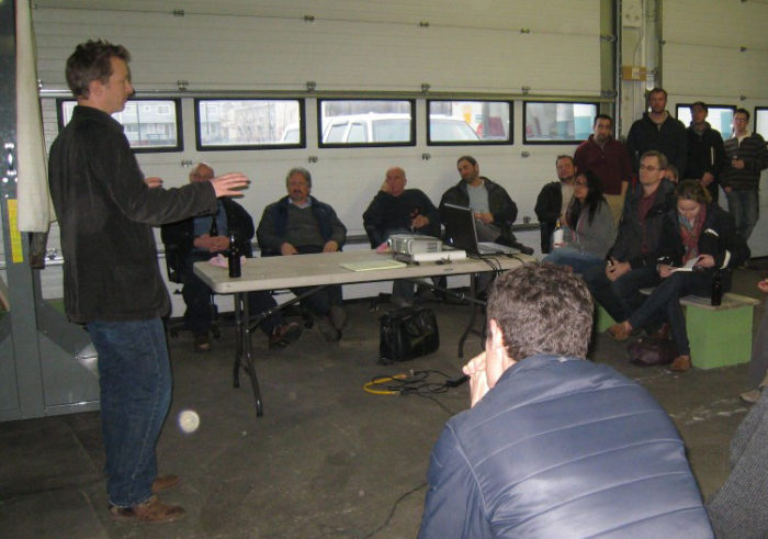
The April 5, 2011 meeting began with an informal social of beer, hot dogs, chips and other nutritious delights (not a canapé in sight). Our architect, Chris Briley
, came prepared with architectural scale (1/4″ = 1′) drawings of our project. For some 2 1/2 hours, the 50 participants questioned, poked and prodded Chris on the whats and whys of the German Passivhaus building standard in general, and the particulars of our project.
Energy modeling shows that the heating load is high
While there was a good-natured banter back and forth, the questions were both perceptive and probing. No softball pitches here! It was sobering to have heard earlier in the day from Marc Rosenbaum, our Passivhaus consultant, that the initial heating load calculation was 7.7 KBTU/sq. ft./yr. versus the Passivhaus standard of 4.8 KBTU/sq. ft./yr. The design is reasonably close, but not up to standard yet.
Here’s a sampling of the discussion:
- Why do most Passivhaus buildings look so ugly (homes designed as rectangular boxes are more economical to insulate to the very high Passive House standards)?
- How do you translate the Passivhaus heating/cooling and total source energy standards to units that are easier to understand? (For the former, a 2,000-square-foot home can expect to use only 100 gallons of oil per year for heating, which is dramatically less than other Maine homes; the latter standard for source energy is harder to compare.)
- Are there follow-on tests that confirm the continued air tightness of Passivhaus homes in the years after they are certified and occupied? (Post-occupancy testing has just started; some early results indicate that performance drops slightly in the years following certification, perhaps as a result of occupant behavior, drying of building components.)
- Does it make sense/”cents” to achieve the full Passivhaus standard if it is cheaper to install some active alternative source (e.g., solar) to achieve that same level of energy efficiency? (Hmmm….)
How durable is Zip System tape?
There were numerous comments regarding the design of our home:
– Suggest changing the perimeter drain in the room designated as the study so that it is at the same elevation as the footer (yep – drawing showed it just below grade)
– Do you plan to include fly ash into the concrete to reduce the carbon penalty for concrete production and increase strength (will investigate it’s availability – expect that will contribute to LEED points)
– Consider an alternate means for subslab insulation that runs the EPS insulation continuously below the slab and between the footer and the ICF basement walls (will consider)
– Consider using Grade D building paper instead of Tyvek or Typar. It’s much cheaper and just as effective (hmmm…)
– Consider adding fibermesh to strengthen concrete for floors and reduce chances of cracking (will consider)
– Consider alternate means of attaching the floor joists to the ICF walls to achieve greater insulation at that weak point in the building assembly. Options discussed included using Simpson strong ties, using an ICF course with an interior brick ledge to support the floor joist (will consider)
– Consider wrapping peel-and-stick membrane around the top of the main floor top wall plate as a means on providing a continuous air barrier from the top of the sheathing to attic (will consider)
– Adding Tyvek/Typar is cheap insurance against long term tape failure at the joints of the Zip wall sheathing (agreed — that’s why it’s included in the wall cross-section)
– Liked the high-compression insulation as a means of creating a thermal break between the concrete interior of the ICF wall and the concrete footer (engineer participants confirmed that the rebar ties between the ICF and footer will transfer the weight between these two sections of concrete – be sure to specify the proper size rebar!)
Probing questions yield a better design
I thought Chris did a masterful job presenting the details of our project and fielding comments. I am thankful for the insights and suggestions offered by participants in helping make our project even better.
Kudos to Maine Green Building Supply for initiating and sponsoring these monthly sessions. I look forward to attending future sessions. Knowledge is a powerful force!
The second article in this series is Goodbye Radiant Floor. Roger Normand’s construction blog is called EdgewaterHaus.
Weekly Newsletter
Get building science and energy efficiency advice, plus special offers, in your inbox.


7 Comments
Connecting the wall framing to the rest of it.
Rodger & Chris Briley,
I would avoid the use of an impermeable peel and stick as an air barrier. There are air barrier membranes that are made to do that, and are permeable. Main Green Building Supply now sells the Siga products (as we do also). Here is a pic of how some of us treat the transition applications out in the West by splitting the membranes into strips, placing them on the framing joints and then connecting them to a full membrane later.
Works great!
Good looking project and you are in great hands with Marc Rosenbaum. (Lucky you!)
albert
The Small Planet Workshop
Air barrier over top plate
Is it necessary to add an air barrier there when you already have to the top plate to block airflow? Wouldn't the solid wood be adequate to stop airflow if the wall and ceiling air barriers were simply lapped over the vertical 1.5" edges of the top plate and covered with the sheetrock?
Air barrier over top plate.
Ron,
By today's standards, building a passive house is working in extremes. In later years it will probably be "normal". Although the pictures don't show it, the common application that this deals with is: connecting exterior taped sheathing to the underside of the lid. I don't have good pics for that at the moment. It's going from outside to inside through the wall plates.
Since the requirement is 0.6 ACH 50, then all those little leaks of plates butting, stacking, and shrinking in a wall section, add up when you consider the liner length of the wall plates. Many don't feel that they can get as good a seal as they like with just face taping the inside. There is still the inner face of the exterior sheathing against the studs & plates that will inevitably have gaps...
Getting an envelope "that tight" is a pretty interesting excursive...
Concur With Albert
We will not be using the peel and stick membrane as suggested in this forum, so we've already taken your advice Albert. In fact our solution is to have a plywood gusset at the top of the wall and also to sheath the underside of the trusses in 1/2" Advantech. This allows us to be able to test the shell before the gypsum wallboard trade arrives on site. Heck, even before the insulation goes in. We will be able to find leaks and seal them. We should, almost immediately, know what our ACH50 will be at its best. It will then be up to the builder to maintain it with the installation of any penetrations.
Chris
Air barrier over top plate
Albert,
Okay, I understand that objective. I built a house where I had to shift the vapor barrier from the exterior of a first story wall to the interior of second story wall. I used aluminum sheet to continue the barrier under the second story floor plate. The sheet was folded to transition from vertical on the exterior to horizontal under the plate, and back to vertical on interior.
But that shifting from outside to inside is not what is happening here, so I do not understand the reason for the barrier being run on top of the wall top plate as shown here. As I understand it, that taped seam will be just a taped lap without being sandwiched between framing members as a backing.
It seems like it would be harder to get and maintain air tightness with that approach, as opposed to just lapping, caulking the edges of the barriers against the sides of the top plate, and compressing them under the sheetrock.
Chris, Sheet goods for the lid
Chris,
Sheet goods for the lid have worked well out here. Friends at the Artisan Group http://artisansgroup.com/ & https://www.greenbuildingadvisor.com/blogs/dept/musings/more-passivhaus-site-visits-washington-state, who kick a$$ at this have found that after the 5th Passive House, they've noticed that the bottom of the trusses are not true and that they have to spend a lot of time shimming the sheet goods to get an even plane.
This may be where membranes come in handy since they can span the bottom of the trusses quickly. We are thinking of hanging the 2x6 service cavity (shown in the second link above) with Simpson angle braces at long intervals with good truss head screws to establish a true plane. Screw them in or out to level, then shim and fix permanently at truss intervals. -might work...
Nice idea on the gussets.
Btw... Tape usually sticks well to the smooth face of regular OSB. You don't have to use advantech...
Ron, I can't say for sure...
Ron,
I can't say for sure. That wasn't my project. Mark in our office helped with that one. The builder was kind enough to share pictures with us. I was looking for membrane hanging over top plate pics and found those in our files. I probably confused the matter.
IMHO I think both will work fine. In my experience, fewer joints make a better seal, and flat joints are easier to manage than 90 angle joints, such as lid to plate.
Since it's just "plugging holes", there are all sorts of good ways to do it. We continue to learn how to use our air sealing materials better with every project and builder we get to be involved in/with...
Log in or create an account to post a comment.
Sign up Log in