

More Building Science


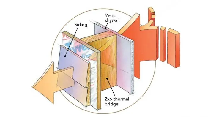
If you look at an insulated wood-frame wall with a thermal camera, you’ll see a pattern of vertical lines representing the studs. Studs are an example of a thermal bridge—a portion of a building assembly with a higher thermal conductivity than adjoining areas.
Thermal bridges increase heat transfer through the building envelope, driving up heating and cooling bills. One study estimates that thermal bridging accounts for 10-15% of U.S. residential energy use. In winter, thermal bridges also create cold spots where condensation—and mold growth—can occur.
There are three types of thermal bridges:
Clear-field thermal bridges are distributed throughout a surface like a wall, floor, or roof. The bridging elements include framing like studs, joists, rafters, top and bottom plates, and headers. As we’ll see below, the effects of clear-field bridging can be modeled as a reduction in the thermal resistance of the entire surface.
Linear thermal bridges include concrete slab balconies and masonry party walls extending through the thermal boundary. Linear bridges can occur in any building type but are especially significant in commercial and multifamily buildings. Heat transfer through linear bridges increases with length.
Point thermal bridges occur when a beam or pipe passes through the thermal boundary. Heat transfer through point bridges depends on the number and type of penetration.
In this article, I’ll focus on clear-field thermal bridges in wood-frame assemblies. After a quick review of the relationship between thermal resistance and heat transfer, I’ll discuss series and parallel pathways. Understanding these pathways will allow us to calculate the effects of thermal bridging on overall R-value. I’ll wrap up by discussing practical strategies to reduce clear-field thermal bridging.
Heat loss, R-value, and U-value
The rate of heat transfer through an opaque surface like a wall increases with its…
Weekly Newsletter
Get building science and energy efficiency advice, plus special offers, in your inbox.

This article is only available to GBA Prime Members
Sign up for a free trial and get instant access to this article as well as GBA’s complete library of premium articles and construction details.
Start Free TrialAlready a member? Log in


13 Comments
Thanks for the interesting article. Many double stud wall assemblies on this website and others align inner and outer wall framing to be almost identical. How much does inner and outer wall framing alignment affect the thermal bridging calculation? In winter, as heat moves through the inner wall framing and into the continuous insulation layer between the inner and outer walls, it presumably has some lateral transfer within that insulation layer rather than remaining confined to a 1.5” wide flow path, right? Maybe this is what you’re referring to with the more advanced isothermal planes method available in WUFI and THERM? If it really makes a significant difference, offsetting the inner and outer wall framing would seem to be a low cost (almost free?) modification to further reduce thermal bridging.
Steven Winter Associates studied the double stud "staggered vs. aligned" problem back in 2009. Takeaway--for the most part, staggering the studs between the two layers doesn't matter that much.
Thanks for posting that. My gestalt was that staggering studs wouldn’t make that big of a difference. I agree, that this seems to support that. However, I now have a different question. This single THERM simulation with unrealistically low framing factor shows less benefit than I would have expected from the continuous insulation layer. In particular, as the report author points out, the 7 in gap-less double stud has less than expected thermal bridging impact.
Aligned studs:
R 23.8 / 7 in = 3.4 R/in
R 27.8/ 8 in = 3.475 R/in
R 31.5/ 9 in = 3.5 R/in
Is that just because of the unrealistically low framing factor?
That is fascinating. Thanks for sharing, Kohta. We've built a bunch of 10-12" double walls and stopped worrying about alignment years ago, but still the 7" is counter-intuitive, isn't it?
Yeah, it's hard to make sense of the performance of the 7" wall. It almost gives the impression that thermal bridging--in any case--really isn't a thing. How do we square that? Something seams off.
Good article Jon. One bit that's missing is that heat doesn't recognize parallel path. It takes whatever the path of least resistance is. A bit of heat that encounters a sheetrock wall 2" over from a stud, so for us 'aligned with the cavity insulation', won't choose the path through the insulation but will instead travel laterally through the sheetrock to the stud, through the stud, and then out on the other side. Thus the framing factor is effectively greater than the stud width.
You can see this on any thermal image of a stud wall. The heat sink of the studs doesn't appear as 1.5" but much wider. This is heat leaving the building. The actual framing factor is probably twice or more the stud widths.
This is worse in a wall cavity that is not fully filled as a bit of heat encountering the sheetrock in the middle of the cavity that would normally find the path of least resistance to be through the cavity insulation may now find a lower resistance path through the air to the side of the stud.
It's inaccurate to say that heat takes the path of least resistance. It will take all paths, but at different rates proportional to the r-value of those paths. I do agree that the effective framing factor is more than just the area of the framing, and I am curious what that adjustment would be.
Yes. I said 'a bit of heat' for that reason though could have stated it better. I always find it difficult to discuss amorphous things in an understandable way :-)
Assuming an IR image is somewhat accurate (it's not but let's not let that stand in our way) then looking at a waveform or spectrograph of a B&W IR image might give us a clue. For one wall I looked at the actual framing factor is about 2.7x the simple framing factor.
I'm out of practice with Therm, otherwise I'd just do this, but it would be pretty easy to model a standard wall assembly in Therm, then do the more "naive" parallel path calculation by hand and compare the results.
What's the typical margin of error on the standard parallel path calculation compared to Therm?
And what's Therm compared to physical measurements? (I'm sure there are some papers about that somewhere).
The simple parallel path calculations are a simplified model, so they aren't perfectly accurate, but is the level of inaccuracy something that actually matters in the context of designing a building? Would the naive parallel path calculation vs a hypothetical 100% accurate calculation actually result in you making different design decisions?
See reply #3 above, which includes a THERM result for a 7" cavity thickness with 2x4 studs aligned and touching, same as you'd get with a 7" wide stud.
R-23.8 is the THERM result using
Cellullose Insulation R 3.6/inch
Softwood Framing R 1.0/inch
Exterior Plywood R-0.6/inch
Gyp board R-0.9/inch
If I try to replicate that using a simple parallel path calculation, I get an effective stud width of 0.89 inches--smaller than the actual stud, not larger.
The parallel path calculation assumes the whole drywall is at the same temperature. The fact that it's colder near the stud means less heat flows through the stud than the simple parallel path calculation indicates, not more.
Thinking in 2D is harder than 1D!
"The fact that it's colder near the stud means less heat flows through the stud than the simple parallel path calculation indicates, not more."
I think you might have this backwards? Colder near the stud is indicating that more heat is flowing through the stud - that's why it's cold there. That cold is kind of like a vacuum of heat - and more heat in the ambient air will flow towards it than towards the warmer parts of the wall.
Both are true--you just have to be really careful to think through what you are comparing.
1. "Colder near the stud is indicating that more heat is flowing through the stud - that's why it's cold there. " Yes, it's colder near the stud than in the middle of the cavity. That's evidence (not a cause) that more heat is flowing through the stud than is flowing through the cavity, on a per unit area basis.
2. "The fact that it's colder near the stud means less heat flows through the stud than the simple parallel path calculation indicates, not more." Notice I already have the "than what" embedded in that statement. And it's different. So both conclusions can be correct. I perhaps wasn't very clear though whether I meant that it's a cause or evidence. I meant that it's a cause.
The calculation is based on ΔT across the stud being the same as ΔT across the cavity. But ΔT is lower across the stud, and we all know that Q = ΔT/R. So it's lower heat flow than it would have been with the same ΔΤ across the stud as elsewhere.
Summary: the lower temperature of the drywall at the stud is _evidence_ that the heat flow per unit area is higher at the stud than through the cavity. And it _causes_ less heat to flow through the stud than would otherwise flow. The different "thans" in those two sentences are key.
Like I said, that's tricky to reason through, which is why we have THERM, and the results show that the concern about the effective framing factor being worse than actually is not something we need to worry about. That's good news.
--> "That cold is kind of like a vacuum of heat - and more heat in the ambient air will flow towards it than towards the warmer parts of the wall"
Strictly speaking, those colder parts of the wall are simply not radiating as much heat back into the room as the warmer parts. They do not 'attract' heat like a magnet or vacuum, meaning heat does not redirect itself to take that path vs any other.
This helps to explain/affirm that the more highly conductive path will be colder on the room side, not warmer-- because more heat is passing through but no extra heat is attracted to replace it.
Electric analogy: the room is (mostly) like a constant voltage source, rather than a constant current source. Adding more conductive paths (decreasing total circuit resistance) will increase the total current (analogous to heat flow), but will have no effect on the current across other existing paths.
Log in or become a member to post a comment.
Sign up Log in