

More Building Science


I’ve written previously about the load calculation and equipment selection process I went through for the new Mitsubishi* ducted minisplit heat pump in my house. Now it’s time to take a look at the design and performance of the duct systems for the two air handlers.
Laying out the ducts
The schematic diagram below shows the three zones for our main floor, two of which are served by the ducted minisplit. On the left (green) is the bedroom zone, and on the right (pink) is the common area zone. The sunroom is getting a new ductless minisplit this week but currently has no direct conditioning. (I discussed the imbalance created when I open the sunroom doors in my previous article.)
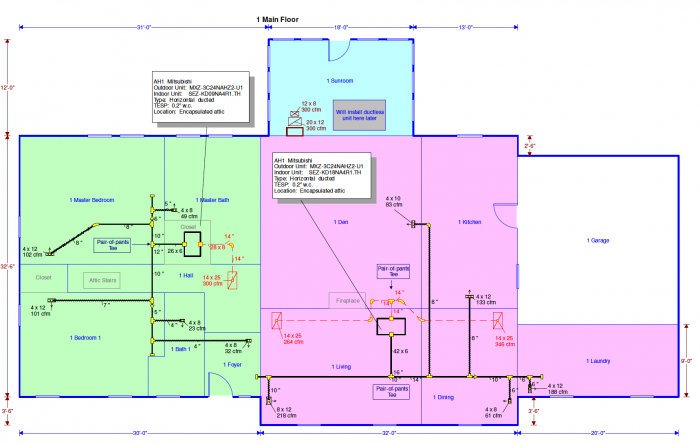
The first thing you might notice when you look at the duct plan is that there seems to be a lot of ductwork for a couple of low-static air handlers. As I wrote last year, the length of all the ductwork isn’t what determines how well an air handler will move air. It’s the resistance. Even with a low-static air handler—and these are designed for up to 0.2 inches of water column (i.w.c.)—you can have a long duct system if you use good fittings and keep the velocity low.
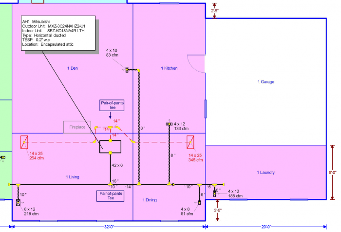
So you can see it better, I’ve included the two zones as separate diagrams below. In the common area zone, we’ve got five supply vents and two returns. If you’re wondering why the return trunk line has those two extra 90° turns on the left and two 45s on the right, well, that’s because reality gets in the way sometimes. I designed that trunk to be nice and straight, but the fireplace and the height of the roof interfered. So we had to put some extra turns in.
Another thing you may wonder about is why I have a supply vent in the living room design for 218 cubic feet per minute (cfm) of air flow. That’s a lot for one vent. We usually try to keep each vent to 150 cfm or less, but I couldn’t find a good way to make that work here. All the supply vents are curved blade registers so most of the air shoots across the room, aided by the Coanda effect. It’s the only place in the house where we can feel air blowing on us, but it’s not a problem in that location because we’re usually just walking through.
The bedroom zone, shown below, also has five supply vents but only one return. We didn’t have to make any adjustments to the layout in this system.
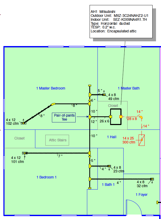
The three filters on the two air handlers are all the same size. Although it shows 14 inch x 25 inch on the diagrams, the supply house didn’t have that size available so I went with 16 inch x 25 inch. My first choice was 14 inch x 25 inch so the installers wouldn’t have to cut any ceiling joists, but cutting them and putting in headers wasn’t that difficult for them.
Designing for low resistance
We use Wrightsoft’s RightSuite Universal for our HVAC design at Energy Vanguard, and that’s helpful in laying out the ducts and checking the velocities in each section. We can get good air flow by doing three things: using good fittings, keeping the velocity as low as possible in the ducts, and following my two rules for flex duct (use it only for straight run, and pull the inner liner tight).
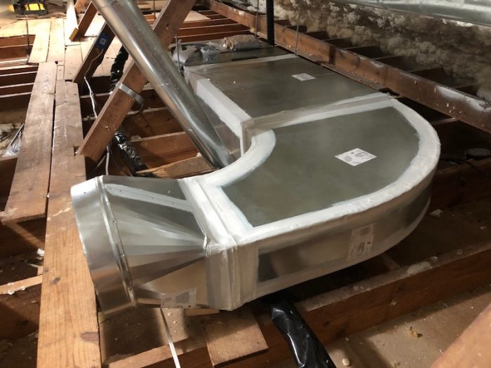
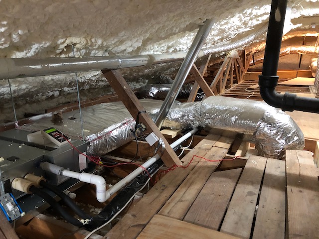
The lead photo for this article shows me with a pair-of-pants tee used on one of the air handlers. The photo below shows a nice radius elbow on the return side of the air handler serving the bedrooms. Those fittings make a big difference, but a lot of people look at the wrong side of those turns. It’s the inner part of that turn (the throat) that has the most impact on turbulence. I see a lot of elbows that have a nice curved radius on the outside (the heel) and a sharp 90° turn on the throat. Don’t do that.
The other factor we use when we design duct systems is the velocity. Keeping the velocity as low as possible—really low in conditioned space, higher in unconditioned attics—keeps the resistance low. Since the pressure drop changes as the square of the velocity, cutting the velocity in half (say, 450 fpm instead of 900 fpm) reduces the pressure drop to a quarter of what it would be at the higher velocity.
No matter how you go about sizing the ducts, you want to end up with low enough resistance to get good air flow without having to use a lot of energy in the blower. The measure of how well you did in your design is the total external static pressure.
The proof of the pudding…
…is in the testing. (By the way, I’m sure you know the proof isn’t in the pudding, right?) With these low-static air handlers, we want to keep the total external static pressure below 0.2 inches of water column (i.w.c.). How well did we do? The photo below shows the reading for the air handler serving the common area zone. That’s 0.14 i.w.c. with MERV-13 filters in the return filter grilles. Pretty good, eh?
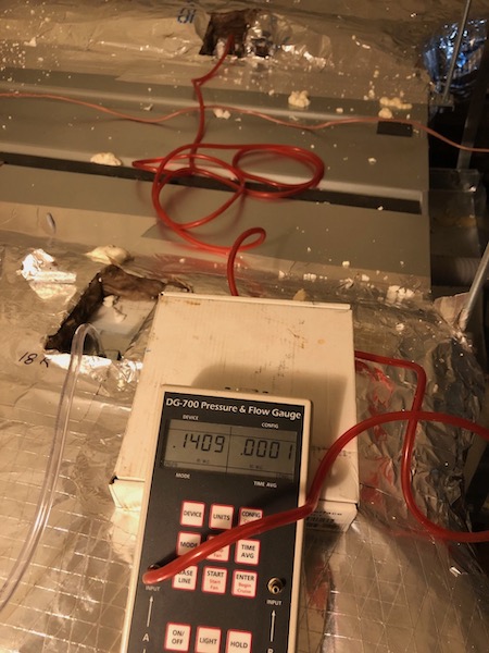
I’ve written in detail about the filter testing I did when I changed out the dirty MERV-8 filters that we used for nearly seven months and replaced them with clean MERV-13 filters. (If you didn’t see that article, you should go read it so you can find out which had the higher pressure drop—the dirty MERV-8 or the clean MERV-13.) The brand new MERV-13 filters I just installed had pressure drops of 0.08 to 0.09 i.w.c. What that means is the majority of the pressure drop in the whole system was across the filters. The total was 0.14 i.w.c. for the common areas with a filter pressure drop of 0.09 i.w.c., meaning the rest of the return and supply ducts, fittings, coil, balancing dampers, and supply registers had a pressure drop of only 0.05 i.w.c.
In the photo below, I measured the pressure drop for the return duct on the bedroom zone. The clear hose measures the lowest pressure in the return plenum near the air handler, and the red hose is measuring the pressure at the bottom of the elbow right above the filter grille. That filter had a pressure drop of 0.08 i.w.c., and the total external static pressure was 0.13 i.w.c., again leaving 0.05 i.w.c. for everything else.
That return duct has a rigid elbow, a short piece of flex duct, a transition piece from 14 inch round to the rectangular radius elbow shown two photos above, and a straight section of rectangular plenum. The pressure drop through all of that was—are you ready?—an astonishingly low 0.0014 i.w.c. Does that blow your mind?
I didn’t measure the pressure drop across any of the supply duct pathways, but I think they’re probably similarly low. Most of that 0.05 i.w.c. of pressure drop probably happens across the coil in the air handler.
So far, the system has performed admirably well, not only in terms of pressure drops in the ducts and across the filters but also down below the attic where we spend our time. It’s super quiet. The distribution in the rooms is really good (with that exception about the sunroom); I haven’t had to mess with the balancing dampers at all. And, although I haven’t measured it yet, I’m sure the energy used to move the air is really low.
-Allison Bailes of Atlanta, Georgia, is a speaker, writer, building science consultant, and founder of Energy Vanguard. He is also the author of the Energy Vanguard Blog. You can follow him on Twitter at @EnergyVanguard. Photos and illustrations courtesy of the author.
* Disclosures: Mitsubishi gave us a discount on the equipment and Canton Heating & Air gave us a discount on the installation. I’m really happy with both and would say good things about them even without the discounts, though.
Weekly Newsletter
Get building science and energy efficiency advice, plus special offers, in your inbox.


5 Comments
Looking forward to part 3. A friend of mine just had a Mitsubishi air handler installed in his attic that has insulated flex duct for the bedrooms and it isn't keeping those rooms cool. I believe the contractor is going to change the ducts out . I believe you have the MXZ-3C24NAHZ2 and I was wondering about the cooling range capacity. I've heard different things - anywhere from a minimum of around 12,000 BTUs to as low as 6000. I'm thinking ( hoping) that the discrepancy is that the newer hyperheat model goes down to 6,000 BTUs. Any info you have would be appreciated.
I am in the process of designing a new house using best practices from GBA. I am also following my fathers advice about designing walls so duct work can be properly installed, I.e. 2x6 interior walls so larger ducts can be installed for a slower flow rate., or a hidden 12 inch return from the ceiling. He designed the ductwork for our house and we never hear it run. Two questions. 1 when should the HVAC designer be brought into the process so it can be properly design, framed; 2. Is it still correct to have AC ducts placed 12 inches from ceiling height when there is radiant floor heating, I.e. Warmboard.
>The proof of the pudding…
Yes. So would be nice to see long term temp/humidity data logger data from each room. Perhaps with welserver.com.
Allison, based on my observations you are lucky to have had your plans for 14 x 25 filters fail. In my neck of the woods at least (Ontario, Canada) that's an uncommon size with limited options and few sales/specials to take advantage of. Our furnace was 14 x 25 until I tore off the return elbow and filter housing and replaced it with a 16 x 25 this past winter.
16 x 25 filters are SO much more common here I don't know why just about everyone doesn't use them on any furnace with a big enough body to accept the return... which is most of them from what I can see. The MERV 12 filters I'm using (3M 1500 MPR) are rated at 0.22 in-H2O @ 820 CFM, a good fit for our 800 CFM air handler and 2-ton AC system. I measured across a fresh filter at 0.24 in-H2O with a cheap manometer, and the 3 month old filter that came out was at 0.35 in-H2O. I would have liked to put a taller 20 x 25 filter holder in, but the body of the furnace won't accept a 20" high return.
Common residential HVAC filters all seem to be the same price regardless of size, so I don't know why one shouldn't install the largest filters possible? The one-time price difference of a larger return elbow and filter housing would be lost in the noise.
Allison, thanks for the great article. 2 questions, where is your fresh air intake into your system and what do the squiggly lines represent -flexible ducts as in the kind you need to pull tight? Why didn't you use metal ducts for those?
From an article you wrote back in 2011 and a comment you made to a poster;
Should Flex Duct Be Banned by Green Building Programs?
Posted by Allison Bailes on April 12, 2011
Allison Bailes
Isaac: I'm with you. If I were building or remodeling houses, I wouldn't use much flex. As I said above, I believe that it can be done well, but it's just better to use hard pipe.
When I get the chance to build myself another house, though, my aim is to have no ducts at all! I want to go with ductless heat pumps.
-So why did you not go with ductless this time, instead you choose ducted? Just curious why you changed your mind on your installation.
Log in or create an account to post a comment.
Sign up Log in