

More Building Science


I like minisplit heat pumps, especially of the ducted variety. And because I don’t like to pay for a lot of excess power, I prefer to use ducted mini-splits with smaller blower motors operating at a low total external static pressure. The Mitsubishi units we have in our office and that I have in my home now are rated by the manufacturer to operate at a static pressure of 0.2 inches of water column (i.w.c.) or less.
Now, that’s a pretty low static pressure to work with. A typical conventional heat pump or air conditioner is rated by the manufacturer to work at a static pressure of about 0.25 i.w.c. and 0.5 i.w.c. when paired with a furnace. Actual duct systems usually exceed that number, and the manufacturers have built in extra blower capacity to handle higher static pressure because they know that’s what happens in the field.
Using an air handler with a smaller motor, however, means you have to be careful with your duct design and not squander that pressure. But there’s a little myth that’s taken root among people who have some familiarity with ducted mini-splits but haven’t worked through the technical details.
The myth is this: You have to keep the ducts short when you use a low-static ducted mini-split.
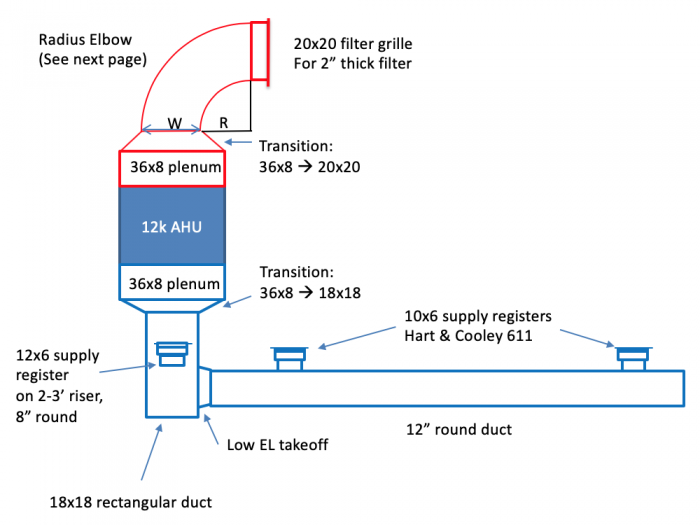
The diagram above shows one that most people would look at and say, “Yeah, that’s a pretty short duct system. That’ll probably work just fine with a low-static unit.” And as a matter of fact, this duct system does work. It works really well. I know because it’s in our office here at Energy Vanguard. We designed it and PV Heating & Air, a local company that does great HVAC work, installed it.
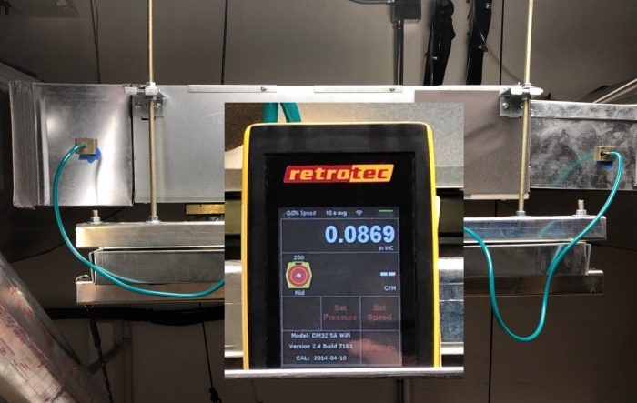
The air handler we used was the Mitsubishi SEZ-KD12, rated for a maximum of 0.2 i.w.c. When I measured the pressure, I found that we’re running at about half of the maximum when the air flow is at its maximum (photo below).
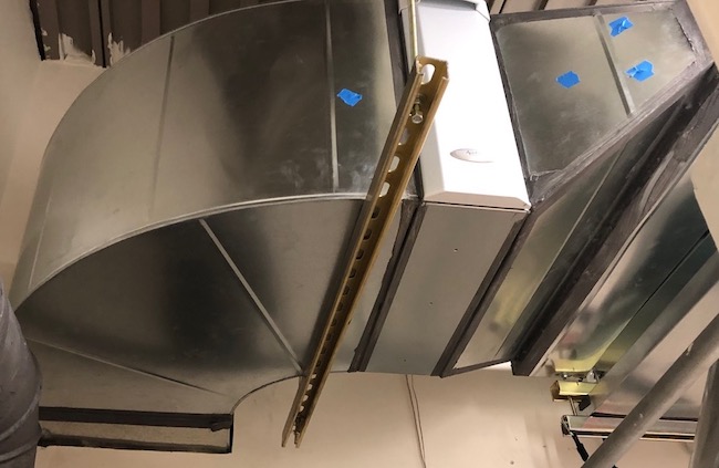
If you look at the duct diagram of our office, you’ll notice a focus on the transitions and the big radius elbow. Getting those things right helps tremendously. Below is a photo of that big elbow on the return side.
The key here wasn’t the total length of the duct system. The two things we did to make this system work so well were:
- Make the ducts larger in cross-sectional area
- Use fittings that are better for air flow (lower pressure drop)
Let me emphasize this point:
The actual length of the ductwork doesn’t matter as long as we keep the static pressure low.
Yes, the actual length does come into play because the total pressure drop increases with longer ducts. But you may recall from my duct design series that the fittings (elbows, takeoffs, boots, etc.) have a much bigger effect on the pressure drop (as measured by total effective length) than the straight runs of duct.
Also, the pressure drop in both the straight sections and the fittings decreases when you keep the velocity of the air in the ducts low. And that’s what embiggening the ducts does for you. (What do you mean “Embiggen” isn’t a word!? It’s a perfectly cromulent word. Get outta here!)
Anyway, bigger ducts and better fittings reduce velocity and pressure drops, allowing more overall ductwork than you might imagine for a low-static ducted mini-split.
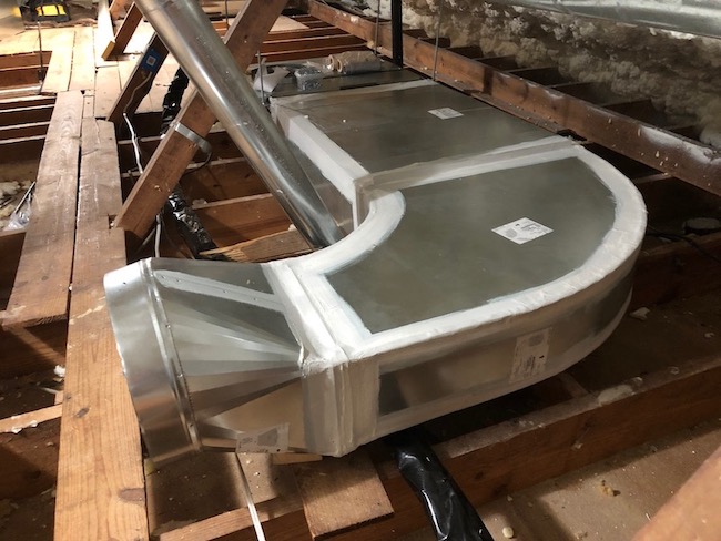
Here’s a shot of one of the returns for one of the low-static ducted units in my house. Again, we have a big radius turn there to reduce turbulence and keep the air flow rate high and the velocity low.
If you look back at the lead photo at the top of this article, you’ll see quite a lot of ductwork in that design. That’s the other low-static unit in my attic. If you believe the myth of short ducts, you might look at it and think, “That’ll never work.”
But you’d be wrong. It works really well. In fact, it’s a perfectly cromulent duct design!
–Allison Bailes of Decatur, Georgia, is a speaker, writer, building science consultant, and the author of the Energy Vanguard Blog. You can follow him on Twitter at @EnergyVanguard.
Full disclosure: Mitsubishi is an advertiser in the Energy Vanguard Blog and gave us a really good deal on the equipment in the Energy Vanguard office and my home. PV Heating & Air gave us a discount on the installation.
Weekly Newsletter
Get building science and energy efficiency advice, plus special offers, in your inbox.


15 Comments
Looking at the first diagram: you don't have to use short ducts, but why didn't you?
Good question, Jon. Deciding on the layout is always a balancing act. The first thing I do is try to figure out the best place to put the supply vents in the room, given how the room is configured and used. In this case, I also considered a potential future renovation I'm thinking of doing. Then I have to find good places for the return vents. The orientation of the air handler has a big impact, too. And then there are the constraints of where I can run the ducts, in this case the encapsulated attic above that zone.
So one thing that often doesn’t get captured in the discussion of available static is how many CFM need to be moved. The static pressure drop in given duct is proportional to the CFM squared. This is important to think about as higher static units often also move more CFM.
To compare available pressures of two units, you should really look at available static per CFM squared. I attached a table where I calculated this for a number of common mini split systems. I multiply the static/cfm^2 by 1,000,000 to get it to a reasonable number.
I find this is not the most intuitive way to think about things, so I also calculate the minimum duct size at 100ft long that would work with the available static and Max CFM.
This is done by solving for D in the following equation:
deltaP/100ft = 2.56(1/D)^1.18*(V/1000)^1.8 where V= CFM/(D/12)^2*3.1459/4
deltaP = static available
CFM = max cfm
D = duct diameter
Still working out the best way to describe all this, but CFM is just as important as available static. Thinking this way makes it clear that you can often replace traditional high CFM air handlers with low static minisplits without much duct modifications.
Excellent point, Matt. When I'm working on a design, I rarely consider the static pressure. I go more by the velocity in the ducts, which is based on the air flow rate and the duct cross-sectional area. Unfortunately, the software we use doesn't adjust the equivalent lengths of fittings for the actual velocity but uses the EL rated at 900 feet per minute (fpm).
Flipping the relationship between air flow rate and pressure drop, we can say:
When you cut the velocity in half, the static pressure drop is cut to a quarter of what it was.
So if the air is moving through a fitting at 450 fpm, the EL is actually a quarter of what the software is using, as given in ACCA Manual D. When the ducts are in conditioned space, we usually design for velocities of 500 fpm or less.
I've written in more detail about this here:
The Best Velocity for Moving Air Through Ducts, Part 1
https://www.greenbuildingadvisor.com/article/the-best-velocity-for-moving-air-through-ducts-part-1
The Best Velocity for Moving Air Through Ducts, Part 2
https://www.greenbuildingadvisor.com/article/the-best-velocity-for-moving-air-through-ducts-part-2
All my initial learning on duct design was from your articles!
It amazes me that the software doesn’t adjust for actual velocity. Does any of the software solve for the full versions of the ASHRAE fitting equations? This is a pretty simple thing for a program to do. Even a full CFD solution is pretty easy these days.
I think mini split manufactures should do a better job of teaching the HVAC industry not to be scared of low static pressure equipment when it runs lower cfm. All of the systems in the table, except the 15k and 18k SEZ, will have sufficient flow replacing a furnace running 1” @ 1100CFM.
> the EL is actually a quarter
But the reference straight duct also has much less resistance at the lower flow rate, offsetting almost all of the effect and making EL (equivalent length) nearly constant (say 5-20% variations, not 400%) with cfm and fpm. See here, fig 2 where there is little change in EL as cfm goes from 100 to 400. Hard to believe that any software or designer doesn't get this at least approximately correct.
“[Deleted]”
Any info on the 20x20 2" filter? (type, MERV?) I have a SEZ-KD15 for a great room (2 16x16 supplies and 2 16x16 returns) where the SEZ-KD 15 was installed with a box directly attached to the intake side of the unit with two 5.625x16.75x2 filters (end to end) which means that, at best, the area is 188 sq in or 1.31 sq ft, which seems way too low. Further, the small cross-sectional area increases the velocity (fpm) (noting high fan setting is 529 cfm) and increased velocity means increased pressure drop. Mitsubishi makes a bigger filter box FBL1-2 with a 12x20x1 filter and a 12x14x1 filter slotted at an angle (at best a total of 408 sq in or 2.8 sq ft). I expect to replace the current filter box with the FBL1-2 and run the Web Eco filters, which have a low pressure drop. Noting that I have a completely separate system for air purification that does not rely on my SEZ-KD15. Any and all advice/comments welcome.
Doesn't the pressure drop of that filter use up a large part of that .2?
>"Doesn't the pressure drop of that filter use up a large part of that .2?
If you choose the wrong filter, yes it does eat up a significant chunk of of the 0.2" static pressure budget at which it meets it's rated specs. Deeper than 2" is somewhat preferable, but not essential to make it work even at fairly high MERV numbers. Large pleated filters that might even be considered "oversized" for some typical small gas furnaces impart far less static pressure drop at the cfm of a ducted minisplit. (At lower than their ASHRAE rated velocities/cfm most filters will beat their MERV numbers too.)
For example, the 20" x 20" x 6" #313 MERV 13 media imparts 0.23" w.c. @ 1200 cfm, but only 0.05 cfm @ 400 cfm (about the mid-speed of a KD15) and less than 0.09" (still less than half the budget) @ 600cfm, above the 529cfm max speed of the KD15. (About a third of the way down , second page):
http://library.coburns.com/specs/CATALOG_Research-Products-Aprilaire_310.pdf
Yes, ~0.05" w.c. at mid-speed is a significant chunk of the design budget, but still only about 1/4.
The #401 MERV 10 media on a 16" x 25" x 6" AprilAire 2400 delivers only 0.05" w.c. drop even @ 600 cfm. (bottom line, second page), and is likely to be delivering nearly MERV13 performance at low & mid speed.
See also:
https://www.energyvanguard.com/blog/do-high-merv-filters-always-reduce-air-flow
Thanks for the filter info. Heard that ducting between the filter and intake of the SEZ-KD, if not tightly sealed, will increasingly suck in air (locally) due to pressure drop of the filter, and with a dirty filter, the greater the risk of sourcing air from unwanted places. Another reason for a separate air purification system. I did follow the data in the Energy Vanguard blog, which is why I am using washable, custom sized Web Lifetime. I will order a custom sized 12x34 Web Lifetime once I swap out the current filter box for the FBL1-2. The SEZ-KD15, with the current Web Lifetime and 2 16x16 supplies with adjustable louvered grilles throws 20ft at 529 cfm. With the prior MERV 8, 2" pleated, the throw was much, much less, insufficient for my great room. If properly set up, the SEZ-KD15 is a nice unit.
>"Heard that ducting between the filter and intake of the SEZ-KD, if not tightly sealed, will increasingly suck in air (locally) due to pressure drop of the filter, and with a dirty filter, the greater the risk of sourcing air from unwanted places."
None of it works well without tightly sealed ducts. Even when fairly dirty the pressure drop isn't very big at <200 feet per minute through a deep pleated filter. (At 529 cfm the velocity through a 20" x 20" filter is still only 190 feet per minute.) The local velocity through any part of a 6" deep pleated filter's medium is much lower still, since it's surface area area is several times the cross sectional square footage of the frame.
An interesting study on local velocity and losses inherent in pleated filters: Media Velocity Considerations in Pleated Air Filtration, https://scholarcommons.usf.edu/cgi/viewcontent.cgi?article=7829&context=etd
The study comments on optimal pleats, more pleats and pleat length "increase the surface area of media that the flow is forced to travel along". Or, as stated in [4]: "The pressure drop increases at small pleat count due to increased media face velocity, and at large pleat count due to increased viscous drag in the pleat spacings."
Seems as if there is quite an art to pleated filter design.
"Optimum pleat count is the number of pleats for a certain height that will minimize the combined pressure loss due to the drop through the filtration media as well as the viscous forces along the flank of the pleat. Less pleats would lead to the velocity of the air moving through the media needing additional driving force in the form of a larger pressure differential, while any more pleats will increase the surface area of media that the flow is forced to travel along as it moves down the pleat."
"As air flows through this pleat arrangement, there are several sources of pressure losses [4]. The first being contraction losses as the flow is directed into the pleat channel. As the flow moves along the pleat channel, both upstream and downstream, there are viscous forces acting between the fluid and the filtration media, this leads to the second source of losses. As the fluid passes through the filtration medium, there exists a third loss due to interaction in the porous zone. Finally, as the fluid leaves the pleated configuration, the flow will experience expansion losses."
And: "a maximum [velocity] at the upstream tip of the pleat which quickly reduces and becomes somewhat uniform along the length of the pleat down to the root. It is posited that the local maximum evidenced in the simulation is due to the change in momentum the flow experiences upon contraction into the pleat. As the flow from the edges of the pleat channel turns to enter into the middle of the pleat . . . ."
Hi,
I had ducted mitsubishi mini splits installed in my new CT home. We have four MVZ-A12AA7 (280-400cfm) and one MVZ-A24AA7 (515-735cfm). All of them have a 4" x 16" x 20" filter box at the unit. I am concerned that the filters will cause a large pressure drop. We used rigid round ductwork throughout the house. Hoping its sized correctly. Many issues with the install, however, so it may not be great. Wondering if I should increase the filter sizes, if possible and if worth the cost. (i had a mechanical engineer involved who would not answer this very question at the time of install...)
Thanks
Andy
Easy answer is just measure the static pressures. An acceptable digital manometer can be bought for $35 on amazon. Plenty on videos on the procedure online.
Log in or create an account to post a comment.
Sign up Log in