

More Building Science


As we replace fossil fuel heating systems with electric alternatives, the green building community will need a broader understanding of heat pump principles and terminology. The better heat pumps are understood—not just by electricians, engineers, and HVAC techs, but also by general contractors, energy auditors, code officials, program implementers, and members of the public—the faster and more smoothly the electrification process will proceed.
One area in which I’ve seen confusion involves electrical requirements for heat pumps. Following these requirements leads to a safe and code-compliant installation and avoids damage to expensive equipment. Understanding a heat pump’s electrical specs can also help identify opportunities for cost savings. These may include avoiding oversized conductors, reusing an existing HVAC circuit, and working within the limitations of the existing electric service.
The rules for designing heat pump circuits are spelled out in Article 440 of the National Electrical Code (NEC). My goal in this article is to introduce readers to key terms and the principles behind them. I’ll also discuss how the sizing rules for heat pump conductors and breakers differ from those for other residential circuits.
For safety reasons, all wiring should be done by a qualified person. All required permits should be obtained before the start of work, and inspections should be performed when the work is complete.
Where to find heat pump electrical specs
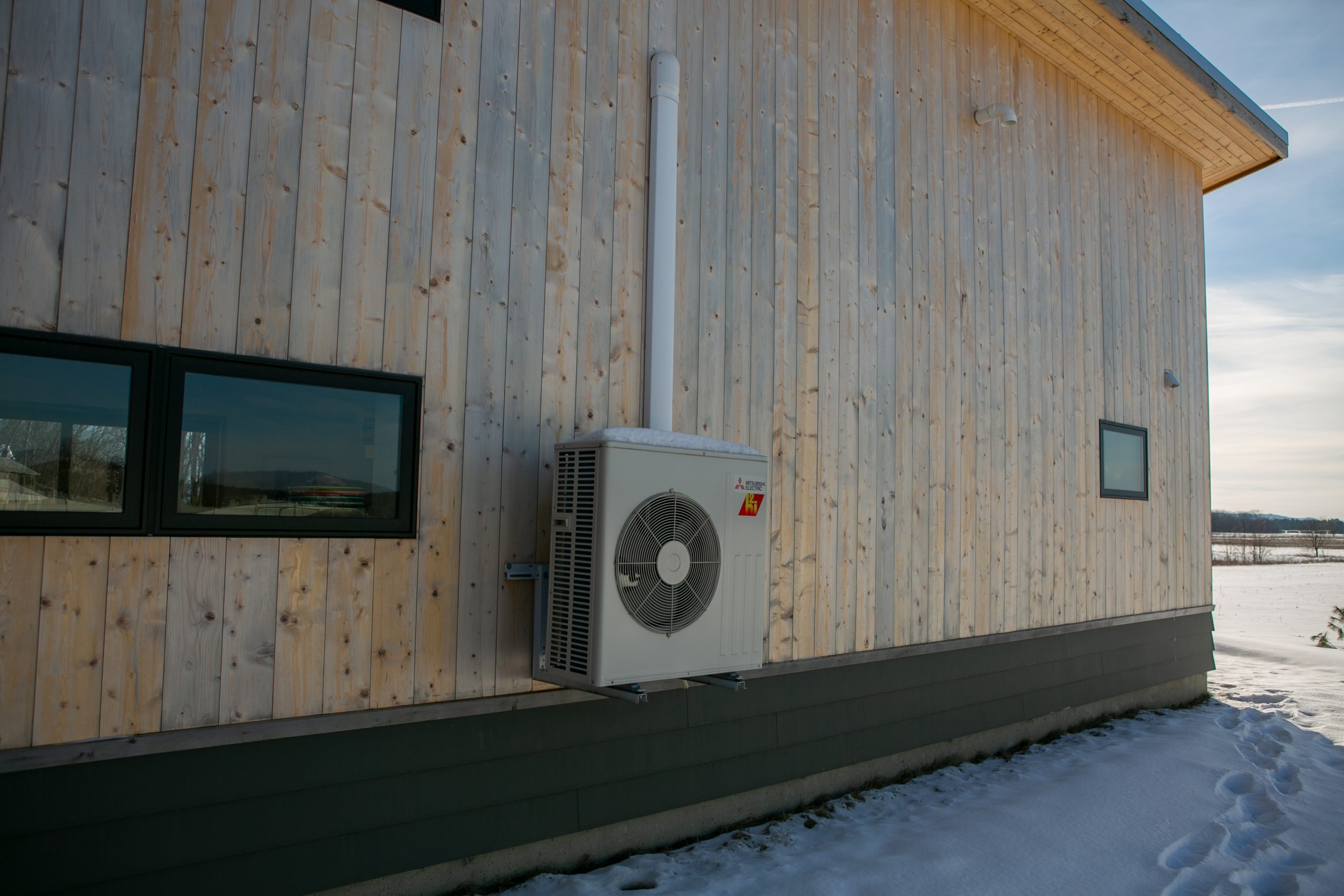
The key electrical specs for any heat pump appear on the nameplate of the outdoor unit. These include the unit’s rated voltage, frequency, number of phases, minimum ampacity rating for conductors, and maximum current rating of the circuit breaker.
If you don’t have the unit in front of you (as you won’t during the design phase), you can get this information from the manufacturer’s literature. I usually look for it on the…
Weekly Newsletter
Get building science and energy efficiency advice, plus special offers, in your inbox.

This article is only available to GBA Prime Members
Sign up for a free trial and get instant access to this article as well as GBA’s complete library of premium articles and construction details.
Start Free TrialAlready a member? Log in


14 Comments
Hello Jon. What is recommended best practice for heat pump surge protection? Is a single surge protector at the main panel adequate, or should one be located at the heat pump? Thanks.
I don't have a universal answer for this. There's nothing wrong with a "belt-and-suspenders" approach if budget and panel space permit. Having both provides redundancy should either the whole-house or the branch circuit surge protector fail (they are designed to wear out over time). Having a whole-hose device also protects other devices and electronics in the home.
That being said, since we started installing surge protectors on our outdoor equipment, we've pretty much eliminated board failures. This includes mostly retrofits where no whole-home surge protection is present. I'm in the Northeast--in more lightning-prone areas the results might be different.
Linking here to a deeper dive I did last year on why surge protectors are important and how they work:
https://www.greenbuildingadvisor.com/article/why-your-heat-pump-should-have-surge-protection
“[Deleted]”
Electrical load is a very hot topic in my Canadian Townhouse complex these days. We are working with a consultant to create some guidlines for limiting the size of a heat pump anyone can install so that all townhouses have the opportunity to install one without triggering the need for an expensive feeder upgrade.
I did reach out to Mitsubishi Canada regarding clarification on MCA and the unit's maximum load and was sent the following document clarifying MCA:
"What is MCA? Minimum Circuit Amps (MCA) is a calculated value that specifies the minimum
main power wire size. More specifically, MCA is the highest steady-state electrical current that
the HVAC unit should see when operating correctly...The selected wire size takes into account the normal current draw, ageing of components and anticipated faults."
Further on in the document is the same formula your article is referenced:
"MCA = [1.25 x Compressor Rated Current] + FAN FLA + OTHER current LOAD"
I'm still confused as the Mitsubishi document seems to indicate that MCA does represent the current to assume for a load calculation, but the formula seems to show a 25% buffer is being added. Maybe that is allowing for "aging of components"? I'll reach out to Mitsubishi again and see what they say.
I guess I need them to confirm that the 25% buffer in their calculation is for the wire sizing and not indicative of the actual maximum current the unit will draw during continuous operation?
The Mitsubishi document uses a verbal definition of MCA different than what I've seen in other places but the same formula. If you look at NEC 220.82 and 220.83, they both use the "Name Plate Rating" for service load calculations. This feels a little vague, since Rated Amps, MCA, and MOCP all appear on the nameplate. The installers I've spoken to about this recommend using the Rated Amps for service load calculations. I'll dig into this a little deeper and follow up.
I think I have a better idea of where some of the confusion arises on this, at least in regard to the NEC. This article was very useful:
https://iaeimagazine.org/2013/mayjune-2013/residential-service-calculations-in-the-national-electrical-code/
The "Standard" method for service load calculations (Article 220 Part III) requires you to add a 25% buffer to the largest motor in the building. In effect, this adds the same 25% to the motor for service load calculations that MCA adds when calculating required circuit ampacity. But only for the largest motor. If you have three heat pumps, and their compressors are the largest motors in the building, you only need to add 25% of the RLA of the largest one.
If you use the "Optional" method (Article 220.82 and 220.83), you don't need to add the extra 25%--you just use Rated Amps. The optional method is approved for single-family dwellings and is simpler and more forgiving than the standard method. I walk through 220.83 in detail here:
https://www.greenbuildingadvisor.com/article/does-your-electrification-project-require-a-service-upgrade
The Canadian Electrical Code calculates loads differently. I'm not familiar enough to comment in detail but did find one article that might be a good starting point:
https://iaeimagazine.org/2013/mayjune-2013/residential-load-calculations/
Like the gentleman from Canada, we in northern Minnesota have a non cooperative electric company when it comes to upgrades. My 1978 house was designed as “all electric’ with ceiling radiant panels and some baseboards. A 200 amp panel was sufficient. After I bought in 2020, I went with a big Mitsubishi outdoor unit and 5 head units. To power the compressor I gave up some of my radiant panels- which I was loathe to do. Those panels, although expensive to operate, will give me heat when the Mitsubishi cannot.
To install energy saving equipment, including an EV charger, I need 400 amp service. That means trenching and contractor resistance (no pun).
EVDuty makes a current sensor that allows you to remove most of its load from your load calculation. Under the Canadian Electric Code at least. It just means that if you are near your limit, then you won't get as much charge to your vehicle. 400 Amp seems like a lot of power for a single home.
The one caveat is that if the current sensor fails, the charger will default to 8amps, requiring you to count 8Ax230V = 1840W towards your load calculation.
https://evdutystore.elmec.ca/products/smart-current-sensor-evccs200
Look at using "Load Share Devices" to help allow you to electrify and stay on a 100-amp 240-volt electrical connection. We have been able to do to this in northern Canada (Alberta).
You can use a "Primary + Secondary" type of Load Share Devise for the Electric Range and the supplementary resistance heater such as the https://www.acdandy.com/motor-control/d-lm.
If you also want an EV charger, use an "energy management" type of Load Share Devise such as the https://dccelectric.com/
robgood,
I'm struggling a bit to see how the necessity to upgrade the electrical service due to increased loads makes either utility "non-cooperative"?
I'm having trouble finding rated amps on Mitsubishi submittals.
For example:
https://mylinkdrive.com/viewPdf?srcUrl=http://s3.amazonaws.com/enter.mehvac.com/DAMRoot/Original/10006\M_SUBMITTAL_MSZ-FS09NA_MUZ-FS09NA_en.pdf
What number should I be using for determining service load calcs? There is no 'rated amps' so far as I can see. There is an MCA number (of 10A in this case).
In this submittal, they've listed the outdoor unit electrical requirements (compressor RLA 9.2 A, fan 0.5 A) separate from the indoor unit (0.65 A), even though they are all powered by the same circuit. Adding these and allowing a couple hundred watts for electronics, this would put the amp draw at under 11 A; the value for service load at 240 V would be ~2640 VA. I think the 10 A MCA in this submittal is an error, but it's somewhat moot, since the smallest new residential circuits are 15 A (14 ga wire). When I've installed this unit, I've used 14 ga wire and a 15 A breaker.
Thanks for the reply Jon. Strange that they wouldn't have a more clear over-all rating.
Is there any work being done to reduce the amount of power required by heat pumps? My main concern is that although they work very well (when properly specified and installed) they draw too much power. With the race to electrify everything, we also need to be finding ways to reduce the load we'll be putting on the grid. For example, is it possible to design compressors that need less power?
Log in or become a member to post a comment.
Sign up Log in