

More Building Science


Let’s say you have an older house. Maybe the laundry room used to be in the basement but got moved to the main floor later. Then someone added a bunch of can lights in the kitchen and family room. Over time, various owners enclosed the porch, converted two bedrooms to a primary suite, and made a bunch of smaller changes, too. For a house with a few decades of such changes, the electrical system can become a mess. If you have an older house, are the breakers in your electrical panel all labeled completely and accurately?
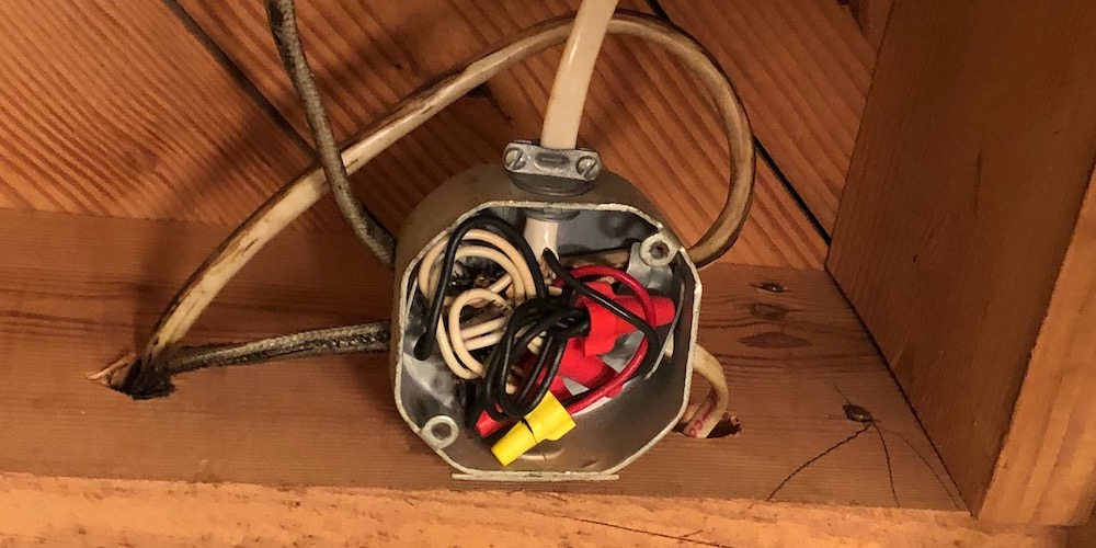
I basically just described my house. Built in 1961, it’s gone through a lot of changes over the years. I can see the remnants of these changes in the different kinds of electrical cable used, the open junction boxes in the basement and attic, and the mess that is my electrical system. The photo below shows at least three different kinds of cable entering this junction box.
An electrician who looked at my house early on told me the whole thing needed to be rewired. Yikes! That sounds expensive . . . because it is! So, my plan is to redo the basement wiring when I remodel. I’ll do what I can with the rest later.
My first step has been to figure out which breakers control which loads.
Electrical safety
Messing with the 110 or 220 volt electricity in your house can be dangerous. You shouldn’t need to open any junction boxes or take the cover off the electrical panel just to map out your circuits. But if for some reason you do find yourself face-to-face with bare copper, don’t trust the breaker. It’s a good practice always to test and make sure the electricity really is off before you start touching the conductors.
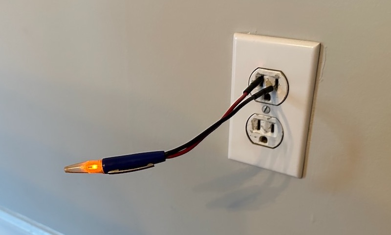
These days, you can find many different devices that can tell you whether your wiring is hot (energized). The photo above shows the simplest type and is one I got from my grandfather. It’s just two leads you use touch to the wires. If the tip lights up, as it is in the photo, the wires are hot. Always test. And then test again to be sure. Above all, call a pro when you need to.
Step-by-step process
Last summer I spent a whole weekend mapping out all of the circuits in my house. I did it myself and made a whole lot of steps going from the electrical panel to every part of the house, flipping breakers and switches.
So, where should you start if you want to do this in your house? That’s easy. First look at the panel to assess what you’re starting with. If it’s labeled, you may have a head start. But don’t automatically trust what’s written there. Use the labels only as a guide.
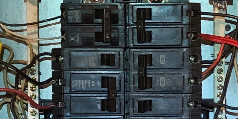
Second, identify the two kinds of breakers in the panel. Some are big double breakers, two separate breakers that switch—and trip—together. Others are single breakers, usually 15 or 20 amps. In the photo of my panel below, there are four double breakers. On the top left is a double 15 amp breaker (two 15 amp breakers ). Right below that is a single 20 amp breaker, then a double 40 amp breaker. The left-side breakers, top to bottom, are for a Mitsubishi ductless heat pump in the sunroom, the now-removed whole-house fan replaced by my attic exhaust fan, and the larger Mitsubishi heat pump that heats and cools most of the main floor.
On the right side is a double 30 amp breaker at the top, another double 30 amp breaker in the middle, and then a single 20 amp breaker at the bottom. They protect the heat pump water heater, the electric cooktop in the basement, and lights and outlets on the back side of the house.
When you start mapping out the circuits, begin with the big, double breakers. They are the ones most likely to be labeled correctly to begin with. The big ones usually protect:
- Air conditioners or heat pumps
- Water heater
- Range and oven
- Clothes dryer
- Electric vehicle charger
There could be other big loads, and you may not have all of the ones above. If you use gas for heating water, cooking, and drying clothes, you won’t have double breakers for those.
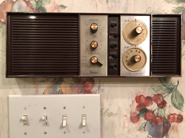
The harder ones to map out are the many small electrical loads: lights, outlets, fans, dishwasher, built-in radio (above), garbage disposal, and anything else hard-wired into the house.
Matching loads to breakers
The easy version of the old-fashioned way to do it would be to have two people talking to each other from different parts of the house. One will stay at the panel, turning breakers on and off. The other person will go to each room in the house as well as looking at exterior lights as the panel person switches breakers.
If you’re doing it alone, you can save some steps when testing outlets by plugging in a radio turned up loud enough to hear at the panel. (Hat tip to Jeffrey Chalmers of Ontario for posting that idea on LinkedIn.) For lights and other loads, you’re going to get a lot of steps doing it the old-fashioned way by yourself.
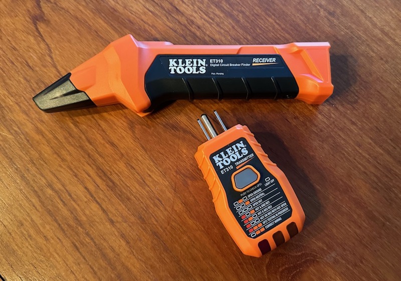
If that’s old-fashioned, you ask, then what’s the new-fashioned way? There are tools available now that can help. The Klein Tools ET310 is one that I tried on my house. Unfortunately, I kept getting false positives. The receiver would light up indicating I had the right breaker, but then it would light up on another breaker as well. But the transmitter (plug-in part) is useful for other things, too, like confirming that a lot of my outlets aren’t grounded. Other people I know have had good luck with these kinds of tools, though, so it may be worth a try.
Another tool that can help is the Emporia Vue whole-house electricity monitor. You can turn loads on or off in the circuits you’ve set up for monitoring and see if they affect the result. It helped me identify a mystery load, which turned out to be the cooktop in our basement.
Whichever way you map the circuits, it’s essential to keep good notes and make sure you’ve got the correct breaker number written down for each electrical load. And then go back and check everything again. The bigger the house and the more complicated the electrical system, the longer it will take to get the electrical circuits all mapped out.
Organizing the results
Once you’ve got everything mapped out, your life will be easier. But don’t stop yet. Organize the data you’ve collected. First, of course, you want a numerical list of the circuits and what each breaker controls. That’s the norm, but most panels don’t give you space to list every load on each circuit. This is especially true for older houses. My busiest circuit, for example, has a dozen different loads in the basement, the main floor, the attic, and even one outdoor light.
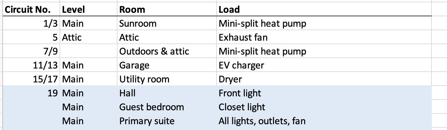
I entered all my circuit information into a spreadsheet on three different tabs. The first tab is the by-circuit information I just described. It’s got four columns: circuit number, level of the house, room, and description of the load. You can see a screenshot of the top of it below.
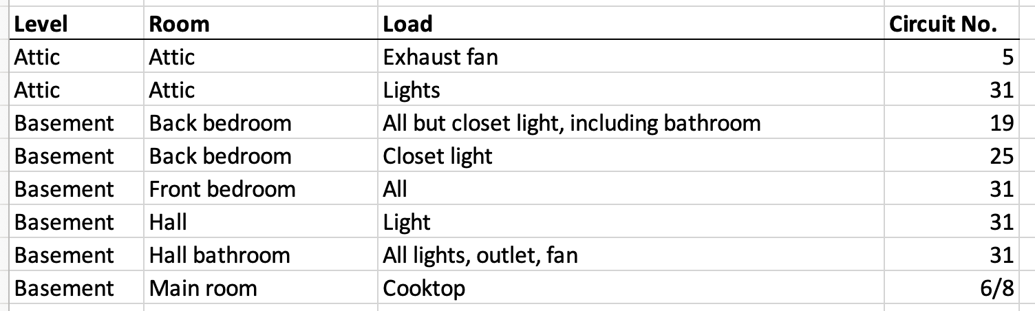
The second tab is the by-load data. This one makes it easy to find the breaker number for any load in any room of the house. It’s actually more useful than the first tab because we usually start with a particular load we need to shut off. Again, I’ve organized my list with the same four categories as the first tab. They’re just in a different order.
The third tab (not shown here) is basically the same info and organization as the first tab, but I’ve put it into two side-by-side sets to match what I see in the panel.
You can take this even further, too. Jonathan Porter, an engineer in Minnesota, made a full schematic design of every circuit in his house. It shows every load, cable, junction box, and breaker. Joe Smith, a contractor in California, labeled not only his breakers in the panel but also the switches and receptacles in the house. Dennis Heidner, an engineer in Seattle, drew a schematic layout of his system and labeled the cables, too. How OCD will you be with your circuit mapping?
A step in the electrification process
If you, like me and many others, are going all-electric, mapping out your circuits is an essential task. In my case, it has helped future work I’ll be doing. My panel currently has a breaker in every available slot. To add circuits, I’d need to get a bigger panel or a sub-panel.
Or I could find circuits I don’t need anymore, and that’s exactly what my circuit mapping efforts helped me with. For example, we have a kitchenette in the basement with an electric cooktop. That uses two slots in the panel for a double 30 amp breaker. We also have a big whirlpool tub we’ll probably ditch and a few circuits with almost no load that we can combine.
In the end, labeling the panel and measuring your electrical use with something like the Emporia Vue makes the electrification process easier in many ways. Have you mapped your circuits yet?
________________________________________________________________________
Allison A. Bailes III, PhD is a speaker, writer, building science consultant, and the founder of Energy Vanguard in Decatur, Georgia. He has a doctorate in physics and is the author of a popular book on building science. He also writes the Energy Vanguard Blog. You can follow him on Twitter at @EnergyVanguard. Photos courtesy of author.
Weekly Newsletter
Get building science and energy efficiency advice, plus special offers, in your inbox.


9 Comments
Allison,
The original labels on my panel only bore a passing resemblance to what they actually served. One very useful thing to do when mapping them is to write the circuit # on the back of the cover-plate for each outlet, switch or junction box you test.
What would be nice if electricians used logic when running circuits and didn't connect unrelated rooms to each other for their own convenience. My house has the lights in the garage, laundry room, and kitchen on the same circuit, along with a couple random outlets including an outdoor outlet. So if i'm running a higher power item outside it can trip that circuit and thus kills the lights. It taught me that when designing houses, to be specific on the electrical plans with how I want the circuits run to ensure areas are logically isolated.
It is annoying but they frequently do that on purpose. Think of how annoying it is when you pop a breaker and it kills everything in the room...might even be a rule about that....
The radio trick is great if you want to find the breaker for one receptacle. But if you want to map out, for example, all the receptacles in the kitchen, that can take a lot of back and forth to the panel.
That's where I think your idea of using the Emporia Vue could make it easier. If you have a medium-size plug-in load, maybe a 100 W light bulb (if you can still buy one of those), you could move it from receptacle to receptacle, seeing which channel it shows up in, without going back and forth. I don't have mine monitoring system (IotaWatt) set up with a large number of channels, but I could move the CTs to the likely candidates for a part of the house, maps those, and move on. You can check the circuits you are monitoring plus one more, but designating the one more by turning it off.
That plan could also work with a clamp meter and some way to display video remotely, whether that's a security camera, a baby monitor, or setting up a zoom meeting between a computer pointed at the meter and your phone.
My final suggestion is that if you make a nice spreadsheet, also print it out and tape it to the wall next to the panel. You might intend to transfer the spreadsheet to the next owner of the house, but there are lots of reasons that might not happen as planned.
Regarding circuit numbers, I prefer to label the wires as they enter the breakers, so the position of the breaker in the panel (which often changes in an upgrade) is not the identifier. A matching # on each breaker let’s you read the system without taking the dead front off and another on the back of the cover plate of each switch & outlet, as mentioned, will complete the work. If you find yourself searching or working on junction boxes, circuit #’s there are also a gift to the next person who opens it. I use books of inexpensive wire labels for the task, they seem to stay put for years and years.
When mapping an entire house, having every light on and a visual indicator in each plug ( I use nightlights with the photocell disabled) can reduce the number of trips you make through the house as you shut off each breaker then note what has changed. For outlets that get missed, I might run an extension cord to the panel from the mystery plug with a tester on the end then flip each breaker in sequence to find the source.
The Emporia Vue is a great tool, especially with the the current transformers for the mains, because it can show the loads that are not running through the individual circuit CT’s, so it speeds up the search for mystery loads considerably. It can also benefits from numbering the individual current transformers to keep your notes straight. If you can’t find an old incandescent bulb, a hairdryer will add a nice 1kw load to any circuit, which is hard to mistake for another cycling load.
Lastly, it’s suggested that the room labels are not based on temporary conditions (like the name of the occupants), but something more permanent, like north bedroom instead of office or guest room. Putting a date on the circuit map will help the next person track any changes made after all your work.
Lots of good tips there. I liked the nightlight one enough that I just bought a 12-pack of night lights for $11 on eBay.
Allison is lucky his 1961 house has grounded circuits, the one I grew up in built in 1961 still had ungrounded outlets.
I think rewiring is pretty extreme[as the electrician suggested] . In my current 1970 house we put in a sub panel and all the new stuff went there. When doing a large reno like we did, you are frequently adding GFCI and AFCI breakers so it is convenient to put those in a new box, along with the new 240v stuff
I think as long as your house is in the grounded/circuit breaker era rather than the fusebox ungrounded era, you are usually in pretty good shape
Here is the zero-(foot)steps method to CONFIRM that you have located the breaker with the tester you are using (Klein ET310). When you switch the breaker off, there should no longer be power to the device you plugged into the receptacle! If you still detect a signal at the panel, you've turned off the wrong breaker. If you do this every time you identify a breaker, you can verify the accuracy of the process.
If you have a friend who is an electrical contractor, see if you can borrow her whole-panel identification tool... you put clips on each of your wires in the panel, then move from room-to-room plugging in a device which will indicate which circuit is feeding that receptacle.
Last tip: identifying lighting circuits can (arguably) be made easier with a similar tester (from Gardner Bender). The plug-in part lacks a ground pin, allowing you to use a two-pin lamp/receptacle adapter by screwing the adapter into the light socket (if the light fixture uses the traditional Edison twist-in socket). You're still stuck hauling a ladder around and climbing it twice per fixture. It seems easier to just walk, but perhaps there are situations where it could be preferable.
My 1978 home (2900 habitable sf in two levels, 750 sf attached garage and entryway) is in Duluth, MN (7) and was designed as an “all electric” house. Back then, that meant radiant panels in the ceilings and some baseboard heaters. All appliances were electric originally. The panel was neatly labelled but additions and modifications have certainly affected its accuracy. I want to keep the radiant heat as backup so I am not going to repurpose the breaker slots. I am adding 200 amps of service in a separate sub panel for heat pumps, ventilation, and EV circuit, etc.
Log in or create an account to post a comment.
Sign up Log in