
Image Credit: All photos and illustrations: Lyndon Than
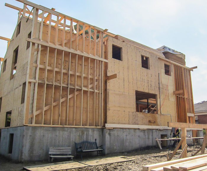
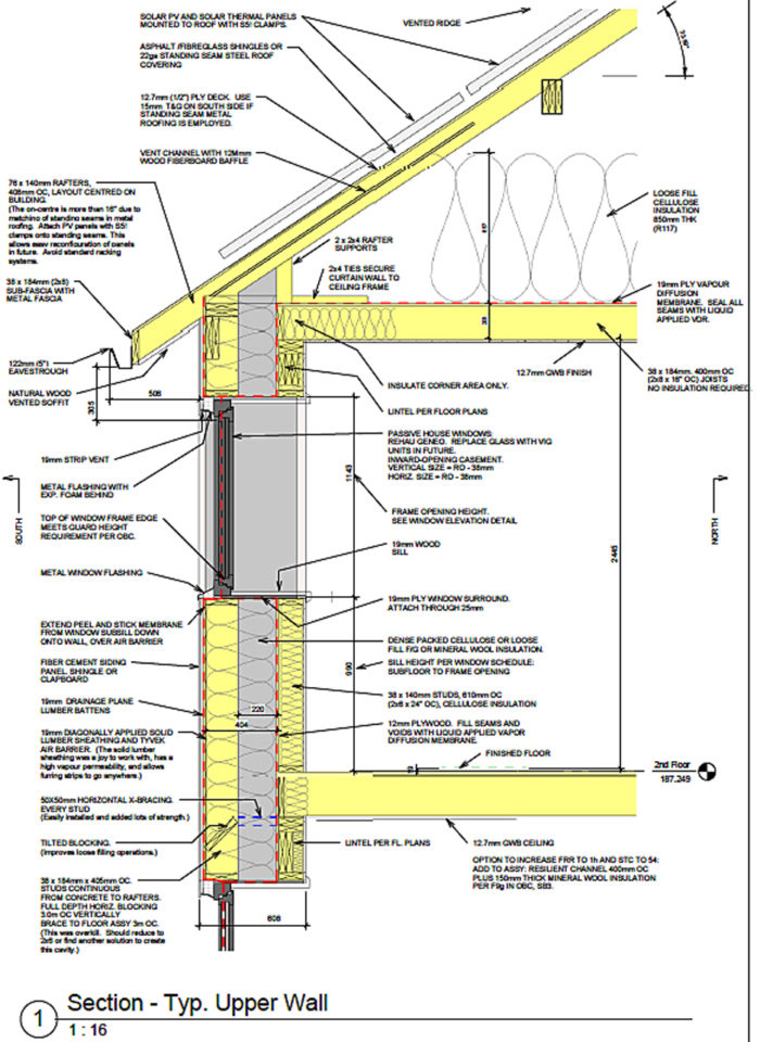
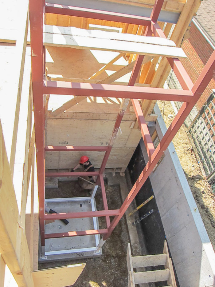
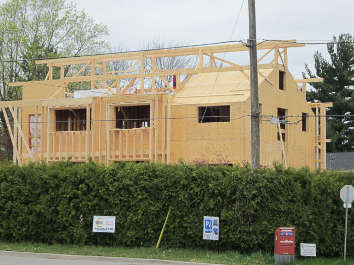
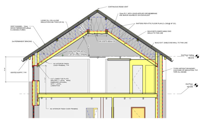
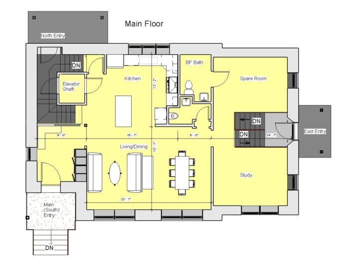
Image Credit: All photos and illustrations: Lyndon Than Exterior walls are sheathed on the outside with solid lumber, applied diagonally, with a Tyvek air barrier. The inner 2x6 wall is sheathed with 12 mm (0.472 inch) plywood with seams and voids filled with a liquid-applied vapor diffusion membrane. Planning to make things easier for parents, the author included an elevator shaft in the house. The supporting metal frame is bolted to a concrete pad at the bottom of the shaft. The elevator itself will come later. The roof has an inner and outer layer, just like the exterior walls. In this photo, the sloped sheathing is the inner roof, with the framing above it added to support the outer roof. The inner roof sections include both a vaulted ceiling in the maser bedroom area, and a flat attic in the other area. In the vaulted section of the roof, 27 inches of cellulose insulation will provide an R-value of about 94. There is an upper and a lower roof surface, each framed with doubled 2x6s. The space between the two is filled with insulation. The first floor of Lyndon Than's Toronto Passive House includes a bed and bath that could be used by a parent, as well as an elevator shaft.
More Guest Blogs


Editor’s Note: Lyndon Than is a professional engineer and Certified Passive House Consultant who took a year off from work to design and build a home with his wife Phi in North York, a district of Toronto, Ontario. A list of Lyndon’s previous blogs at GBA appears below. For more, you can follow his blog, Passive House Toronto.
Our double-stud walls include a structural 2×6 wall on the inside, sheathed on the outside with 12 mm (about 1/2-inch) plywood, then an air gap, and finally a 2×8 wall sheathed with solid lumber. When complete, the walls will be about 2 feet thick and have an R-value of roughly 80.
Once the structural walls were up, we could build the 2×8 frames for the outside and tilt them into place. The 2×8 framing is on 16-inch centers with two rows of blocking and diagonal strapping on the backside (inside). The balloon-frame assembly does not need to meet the tall-wall specs in the code because they don’t hold up the building, but they will be braced to the second-floor assembly at mid-point just the same.
Tilting the 2×8 assembly up into place wasn’t too difficult . We used a chainfall/lever hoist anchored to a large beam in the cathedral ceiling assembly. We also used a rope hoist on the larger assembly. When we didn’t have a large beam to use as an anchor, we used cast-in 1/2-inch anchor bolts in the concrete wall on the far side of the building.
We used two rows of blocking on the 2×8 walls (visible in the photo at the top of the column). In the photo above, you also can see the temporary frame we set up on the ground for building the walls. The frame in the photo is the longest wall we built and lifted in one piece: approximately 2,000 pounds and 20 feet tall. We needed two hoists, but it worked fine.
A double layer roof
The roof, like the exterior walls, consists of two layers, each built with doubled 2×6 rafters. There is vaulted section of roofing over the master bedroom, as well as a flat section over the other part of the second floor. The amount of insulation varies, ranging from about 27 inches in the vaulted section (R-94) and about 32 inches (or R-112) in the attic section.
These double 2×6 rafters turned out to be a fair bit of labor. The building is overbuilt in some areas, but I’m happy about not skimping on the frame and concrete (though it was not overly thick at 8 inches). We do plan to economize in other areas, but not here. With our overbuilt frame, I feel confident our structure will do better in this time of climate change — who knows how much snow will fall next winter, or how heavy future solar equipment may become, or how strong winds and floods may be in the future.
The historical design snow load in North York is about 1.2 kPa (about 25 pounds per square foot), but only 30 km. (18 1/2 miles) to the north, it increases dramatically. The rafters are placed at 16 1/16 inches on center, and are carefully laid out so the pattern is centered on the building. This was to accept the standing-seam metal roof (another story), and so that the standing seams would line up exactly with the 3-inch thick rafters. Thus, the seam pattern on the roof also would be centered on the building.
Don from Heritage Tinsmith told us the standing-seam panels end up being a little over 16 inches on center. All this will allow the solar panel installation to be very strong and secure. It will be easy to keep the 5/8-inch tongue-and-groove roof plywood in line with the rafters. We’ll just provide a 3/8-inch gap between panels to compensate. The fact we are using 3-inch thick rafters means it will be easy to install the plywood regardless.
Planning for solar panels
Our photovoltaic (PV) installation is shaping up. One of the issues was the load-side electrical service, which must be in place first. We really wanted to avoid an ugly overhead service to the building (where birds sit and poop on cars), and the balcony on the southwest corner made it even worse (electrical lines must stay well clear of operable windows and balconies). It also results in these plastic conduits running all over your facade.
We’d been working with Toronto Hydro for quite a long time to get an underground service to the building, but costs and timing were major issues. They requested $1,000 to make a drawing, plus $6,000 to $12,000 for the actual work, and a lead time of three months. We ended up having no time or money for this, so we placed our own utility pole at the corner of our property and made our own underground service connecting to it. From there it is a short run to the city’s utility pole.
One of the design considerations with utility rooms is the following: On a corner lot in the city, you often have a choice as to which side of the property the service comes from, as in our case. With the new smart meters, the electric company is less concerned with mounting the meters close to the front of the house, although it is still preferred. Mid-span connections also are possible, so there was ample choice for us. It’s even possible to have the main service attached to our detached garage and have the house fed from the garage rather than vice versa.
However, getting the service to the electrical panel was tricky because we wanted the electrical/utility room on the north side (back of the house). This is a room without windows, and the location was the farthest from the possible meter locations. During the concrete-wall stage, we placed a 2-inch conduit in the ground around the building from the electrical room to the anticipated meter location — a run of about 50 feet. Later, we dug up the ends of this conduit and routed it into/onto the building exactly where the meter and panels would be.
Connection costs to the city for electricity are minimal (currently the standard price for a permanent connection is $850). We paid $1,500 for the pole installed, and another $1,300 to run the service to the pole, including trenching, conduit, wire, weatherhead, etc. While I’m not thrilled to see another pole in the neighborhood, I do hope that one day I can work with the utility to extend our underground service right up to their pole (only about 6 feet away) and do away with ours.
Planning for an elevator
Another early task was roughing in the concrete and steel support for a future elevator. Why would anyone install an elevator shaft in their house? Can’t people just climb the stairs? It’s better for them. We completely agree. And if you’ve ever used a residential elevator, you’ll find it much slower than the stair.
However, there are some compelling reasons to consider the elevator shaft — note the key word, “shaft.” We are not installing an elevator but we are installing the shaft, which turns out to be quite cheap, even with us doing it the expensive way (more on that below). Here is our thinking: We’ve seen seniors close to us living with their grown children. It is really hard for them to go up and down the stairs. We want a house which is inviting to our parents. We’ve placed a bedroom and full bath on the main floor but there are still stairs to climb to get to the first floor from the outside.
The elevator facilitates at-grade entry into the building. It also allows the grandparents to easily visit their grandchildren asleep in their beds upstairs, or to join the family in the den for a movie. Sometimes a family member is in a wheelchair. The elevator embraces this. Not to mention, any one of us can become a wheelchair user overnight. A house ready for an elevator is one less problem during a traumatic life-changing event.
The elevator also can make moving heavy or large objects much simpler. Space lost to the elevator is not lost unless the elevator is installed. The empty shaft (with floors installed on each level) can serve as pantry, powder room (with plumbing), closet, rock-climbing wall (no floors), etc. We plan to use the shaft in these ways until an elevator is actually installed.
Designed for simple installation
Intended for economical installation, the shafts for residential elevators are intended to be built using regular framing lumber, with studs spaced extra-close and thicker plywood sheathing or 2x12s on the flat. Exact details are per the elevator manufacturer. What is not explicitly laid out is that these walls are intended to be of standard height, framed between floors. The idea is to place the elevator shaft in an area where there is a floor all around it, on all levels.
This did not happen in our design. As our goal was to make the building accessible from the outside, we needed the shaft to be located near an exterior wall, and we ended up placing the shaft inside a wrap-around stair (the stair is placed on the north corner of the building — see the plan below). Thus, a person entering the building from the north door arrives on the stair landing, from which he can enter the elevator.
The shaft walls needed to be about 28 feet tall. This height is an added expense to frame, and if executed in wood, would take up a lot more space (tall wood walls tend to use deep studs too). We therefore made a steel frame; cost of the steel about about $6,000 including delivery. The concrete pad was about $1,000 (labor and materials) and the crane to place the steel was a minimum $600 charge.
In addition, the walls around the stair became very tall. To span the distance from the footings to the ceiling of the second floor, we used 29-foot-long laminated veneer lumber, 1 3/4 inches by 9 1/2 inches placed 12 inches on-center with double king studs. The LVLs were about $4.90 per foot — as costly as steel!
So how does Passive House deal with the elevator shaft? I’ve had no official answer on this question, but assume it will be treated the same as a staircase: Total floor area of the elevator and shaft is not counted. However, since we are installing only the shaft, we are expecting to have the area on three levels included in our Passive House Planning Package calculations.
I’ve also yet to ascertain the energy requirements of the elevator over the course of a year. Again, we will be avoiding this issue for now by not installing the elevator.
Weekly Newsletter
Get building science and energy efficiency advice, plus special offers, in your inbox.


2 Comments
Law of Diminishing Returns
Does anyone know what the Law of Diminishing Returns is? Why not build a house with 200 R in the Attic? Why not 300? Charts showing heat losses at varying R values are readily available and show energy savings diminish at an exponential rate, something like requiring a doubling of R to reduce energy savings by 1/2. The first 5 R saves you a pile, the next 5 half the pile again, the next 10 R saves you 25% of the first 5, the next 20 saves you 12.5% of the first. You are now at an R 40. TO DOUBLE AGAIN saves you 6.25%. At what cost? And at what cost to the environment? How much more concrete, more trees, more plastic, more insulation itself and all associated mining, shipping, and industrial cost.
So why stop at 112 r in the attic and 80 in the walls.
I think saving energy is great, and I do it myself, but I think we have passed into the crazy zone and are a bit hysterical about it.
Nice information! It seems quite interesting how this place is being constructed and I believe when a building gets approved under all safety measures, more facilities can be installed in that building for people. The installation of elevators and other useful facilities is a wonderful job. Thanks for sharing!
Residential elevator company West Palm Beach
Log in or create an account to post a comment.
Sign up Log in