I haven’t given up on concealed duct option
When last we visited our intrepid fool, he had just about given up on the potential installation of a concealed duct unit for his Seattle home.
The task at hand is finding a unit to serve the first floor which consists primarily of an open plan Living, Dining, Kitchen, two bedrooms and bath. The basement furnace that used to serve the house is gone. Heating loads for the first floor rooms are 6862 LV/DN/KT, 1852 in BR1, 2111 in BR 2.
A 9RLFCD would do nicely for the load — the question comes back to duct and static. Based on a few found tools and the five part duct design article from Energy Vanguard, I’ve come up with what I think (operative word) might be a reasonable size and layout. One run however, extends 22 ft and most folks don’t think the low static concealed duct can handle the distance.
The layout image attached, includes what I believe are reasonable calculations. They start with a available static pressure of .36. I reduced that by about .10 to address filters and grills to start at .26.
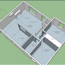
The attached illustration shows the general layout (These runs are under and between the joists in the basement and leading to floor/lower wall vents in the upstairs area. There’s a first floor image to show the room layout.
I applied 30′ per 90 degree bend as part of the effective length calculations. The Friction Rate reductions per 100 ft were drawn from the Super Cool calculator app in the Apple store as well as from the calculations used in the HVAC Calc Residential software I downloaded. I’ve assumed 300 CFM which is the mid point on the 9rlfcd flow rate.
I know this is a lot to ask — but can anyone take a look at this and comment if I’m way off on these numbers — It seems to me that the 9rlfcd is a viable unit taking into consideration the static pressure.
Carlo
GBA Detail Library
A collection of one thousand construction details organized by climate and house part


Replies
Carlo,
The basement should have R-15 against the concrete. You can find additional detail here: https://www.greenbuildingadvisor.com/article/how-to-insulate-a-basement-wall
Is the framing already installed? Is there any evidence of bulk water in the basement?
Hi Steve. Thanks for the reply. The interior frame was installed previously but with no insulation. I managed to slide in 1/2 inch between frame and 8” poured concrete walls. I’ve been filling the 14.5 in spaces between studs with a combination of 1-1.5 in eps to fit behind wiring followed by 2” iso. fitted above and below wiring.
There is an interior French drain feeding a sump basin. I’ve had the place since 2012 and have had no water problems. We do get a bit of moisture around these parts. The basement has stayed dry.
I should clarify, the basement will be finished. There are two bedrooms on the right of the basement/duct layout that are showing less than 1000 btu each heat loss based on the updated insulation. The garage area shown will is also insulated to an R21 on the walls and sills. The traditional garage door is being replaced by a carriage door that will provide a much better seal. Basement heat will be separate. Desire here is to get the main floor on a single zone heat pump.
Sounds like the typical Manual J, S, T, D calculations are needed. They will lead to better answers than "assuming 300 CFM".
Not clear to me is if you could add booster fans if you can't meet specs (register throw, SHR, etc).
Thx Jon. That’s been some of the challenge. Most of the estimates don’t have the rationale. Many over size and in the case of concealed duct assume they can only serve the immediately adjacent room. They also want to install in unconditioned attic. The CFM is from the submittal. Medium speed is 324. Low is 294.
I guess I do not understand what you trying to do. You have a mini split head by the fireplace that should cover the living room and kitchen and a ducted unit should handle the bedrooms nicely. Why are you running ducts back into the living room?
Walt
Thanks Walter -- that was a remnant of an earlier layout -- sorry about that. That is one option I'm considering. I've had some second thoughts to see if I could using a single head ducted option. Based on insights here and elsewhere, tying a second head to the same compressor seems to limit the modulation capabilities of the system. The overall load for upstairs is about 11,000. I guess I'm over analyzing a bit.