Plywood Baffles + Wind Dams
Hi all,
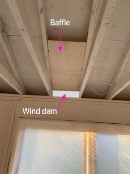
A contractor helping on my PGH renovation (at least I think it’s going that direction 🙂 ) made a mockup of a site-built baffle made from plywood today. It’s a deeper channel than the 2″ advised in previous GBH article, though we could adjust to 2″ if advised. We’re working off this previous GBH article (Thanks Martin):
https://www.greenbuildingadvisor.com/article/site-built-ventilation-baffles-for-roofs
I think it’s best to use foam insulation for the wind dams, as it will also insulate a bit against coming up through vents and into house. There is some leftover 1.5″ or 2″ rigid foam of some kind from previous owner, so I’d like to recycle and use this for the wind dams. We would cut the top at an angle matching angle of baffle coming down, then use caulk or perhaps spray foam to air seal.
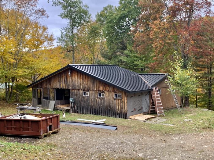
Fyi it’s a gut renovation, so we have things down to studs now. The soffits were just redone, with continuous soffit vents along all exposed parts of truss that lead up to the ridge vents.
Latest building envelope diagram is also attached for reference as PDF. Two images of the new soffits and vents are in the PDF.
Questions:
* Foam for wind dams good idea? Is thickness of the rigid foam enough to insulate from cold seeping in? Or better to double up and get more R value here? If more R value, we’d need to move baffle up a bit in order to fit more foam on top of sill for the wind dam.
* We will air seal on left, right and top of the wind dam. Should we also seal along seams of the baffle up to top? This first test is pretty tight to each side of truss, but if advised, we can air seal here too.
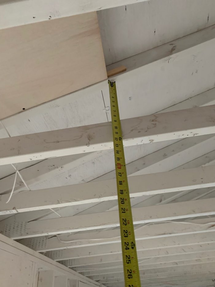
* Insulation will be blow in cellulose to 18″ for R60 (will settle to 16″ according to insulator). To be safe, should we get baffle to 20″ above point where cellulose will start piling up? (bottom of horizontal wood in truss). At the moment, the first demo is at 12″ and clearly we need to go higher. Contractor is trying to be efficient with the ply and cuts.
* Should we stick with 2″ vent space for baffle mentioned in article, or is a deeper version ok too?
* Have not done materials + labor comparison between plywood site built and buying the Accuvent or whatever that 1.75″ advised plastic baffle is. I like the vapor permeability of plywood though, because house had previous mold / moisture problem. Ideally this reno fixes the issue with the plans but maybe best to stick with ply?
Any input is welcome. We should be fine, but it’s a first time building these and would appreciate feedback from more experienced hands…
Thanks!
GBA Detail Library
A collection of one thousand construction details organized by climate and house part


Replies
1" is the code minimum vent space, but many (including me), think it's a bit low. 1.5" is much better, and easy to build since it's the same size as standard dimensional lumber. 2" does allow for more ventilation, but it isn't a standard size, so it's more difficult to build. I like to build 1.5" vent baffles using 1x2 furring strips tacked to the inside faces of the rafters tight to the underside of the sheathing, then tack 1/4" waferboard (cheap version of OSB) to those furring strips. I "tack" these things together using a finish nailer, which makes things quick and easy.
There is nothing wrong with using rigid foam to build vent baffles, and it's done all the time. 1/2" polyiso probably works the best here, since the extra rigidity of the polyiso (compared to EPS) helps a little during installation. You can use thicker rigid foam too, it won't hurt anything, it just costs more and increases the effort required to assemble things. If you have thicker rigid foam available for free, then go ahead and use what you have.
Regarding your specific questions:
Foam baffles work fine. They only really add R value if they are tight to whatever other insulation you're using. This is fine if they are used at the edges, such as to keep loose fill insulation from pouring over the top plate at the eaves. This doesn't work as well if you are hoping to add insulation on top of a layer of an insulating material that will settle and seperate over time. As soon as you have an air gap, convection currents start to flow, and those moving air currents allow heat to flow and cancel out your insulation's effectiveness
It will be much easier to install the cellulose properly if the baffle goes up 18-24" or so above the top of the finished layer of loose fill. The higher baffle helps prevent any cellulose from blowing over the top of the baffle and clogging up your soffit vents. Think of it as giving the insulating crew a bigger target to hit, which makes their job easier.
I'm a bit confused as to what the "2" depth" refers to. Is it the air space / vent gap above the baffle, or the thickness of the rigid foam being used to construct the baffle? I see no problem using 2" thick foam (although it's overkill for this), but a 2" vent space does complicate construction since you can't get standard size lumber in that size. Aside from construction complexity, a 2" vent channel won't hurt anything.
If the vent baffle is only out at the last few feet of roof near the eaves, vapor permeability of the material used for the baffle doens't really matter. The only potential issue with vaper permeability here would be in something like a cathedral ceiling, where the baffle runs the entire length of the rafter bays. In the case of the full-length vent baffle, something that will allow for some moisture migration is probably a good idea to help allow some outward drying from the insulation below.
Bill
Hi Bill,
Thank you for the reply, much appreciated :) Sorry, by 2" depth, I meant the "vent space" that you mention at start of your reply. It sounds like 1.5" minimum is best and if it can be bigger, all the better.
I think we'd do either your version with waferboard or thin plywood. That's interesting about vapor permeability though! We're not doing cathedral up to top, so I suppose other material could work as well in this case.
With regard to rigid foam on hand, the thought is to only use it for the wind dam, to stop air from displacing and pushing the cellulose away near the soffits. And that's a good point you brought up, also to stop cellulose from dumping into eaves. This seems a key place to air seal as well.
Thanks for the suggestion to get 18-24" above top of finished loose fill. I didn't think about insulators potentially spraying it down the baffle!
I forgot to mention in my original reply that air sealing vent channels isn't really all that critical. I don't usually bother to air seal the horizontal pieces (the ones that are parallel to the roof sheathing) at all, and the part you're calling the "wind dam" I usually just foam in place. The idea is to stop most of the wind from getting into the edge of the insulation, which is known as "wind washing", and reduces the effective R value of the insulation at the edge. It's not necassary to air seal the baffles to the extent you would air seal an air barrier though -- usually just physically secure things in place and you're good to go. Extra air sealing won't hurt anything though. Note also that cellulose is less prone to wind washing than fiberglass too, so your insulating material is also better in that regard.
When they blow in loose fill insulation, there is a sort of stream of insulation bits coming out the end of the hose. It's a dusty process, and it's hard to direct it with precision. This isn't usually an issue, but out at the eaves it is harder to get into small spaces. If you have that big vent baffle in place, it's easier to make sure the insulation doesn't go where it shouldn't.
Bill
The challenge with making the vent space taller than the 1.5" needed for venting is that as you move the vent baffle down you are reducing the height of insulation you can blow in. Your photos indicate you don't have raised hell trusses, so your insulation near the soffits will be less than the ideal total anyway - don't further reduce it if you don't need to.
In regards to the wind dam, I've mostly seen them placed flush against the exterior side of the wall framing and projecting up as needed. This allows the blown in insulation to continue over the top plate.
I agree that “ you don't have raised heel trusses, so your insulation near the soffits will be less than the ideal total anyway”
There must be a practical reason or maybe it is an aesthetic thing but if it were me doing a gut job like this, I would think seriously about an air tight bulkhead at the eaves in the interior to add insulation.
I would go one step further and add a 2x4 strapping below the air barrier on the bulkhead and add perimeter lighting under the bulkhead or perimeter LED lighting on the side of the bulkhead directed towards the ceiling.
Lighting is too often overlooked and this is an opportunity to improve insulation and lighting - on a gut job.
This is a great idea for those whose existing or other conditions (height limitations, etc.) preclude raised heel trusses...
It also works well on a slab on grade - you would continue that "air tight bulkhead in the interior" ie dropped soffit - around all 4 sides of the room. The interior side then offers a great location to run duct inside the conditioned space.
Hello to both of you. I wonder if you could attach some visual examples (photos or diagrams) of an airtight bulkhead? I'm not familiar.
At the moment, we're going to add a service cavity on both the ceiling and walls (ceiling will have less space to reduce height reduction). And we're going to add insulation in the wall service cavity to get more R value (+9 I think)
As for those top corners of the room, they do seem like points with a lot less blow in cellulose, ie from maybe just a few inches before wind dam, then slowly higher as truss raises the roof. Beyond blowing a bunch of foam in there for max R value, it seems tough to fully handle. I like idea of a clean 90 degree corner in the room if possible as well.
Fyi for ducting, we're going with ductless mini splits and for ventilation, Lunos wall units, because we're air sealing on inside of house due to difficulty placing exterior rigid and air sealing properly there.
First, amazing drawings. So much detail. Congratulations. This will make the build of the addition and the renovations a lot easier. Wow!
I am concious that you don't have 9' ceilings, but I am assuming you have close to 8' ceilings.
When I looked at your air-sealing detail, I don't think that I would worry about air-sealing the bulkheads if you added some. But I offer a mocked-up version based on your drawing in the attached.
I will provide a few URLs and I hope they work, if not let me know and I can attach the images. The images show both types of lighting I had mentioned.
This is the clearest image I found but still under construction, and focus on the bulkhead on the wall, not the middle of the room.
https://za.pinterest.com/pin/620863498646267659/
This is a good example. You actually see the bulkhead is there to allow for ducting, which is often the case.
https://za.pinterest.com/pin/1001558404608254342/?mt=login
This one shows the bulkhead with down lighting and the stip of LED lighting directed towards the celing is hidden behind a crown moulding.
https://za.pinterest.com/pin/72761350228276470/
This one shows again an example with down lighting, LED strips towards the ceiling with the bulkhead conceiling duct work.
https://za.pinterest.com/pin/68742002394/
This one shows the full ceiling being lowered but you can see that you don't need to do the entire ceiling. This shows how to "hide" a semi-ductless heat-pump head essentially over a closet.
https://za.pinterest.com/pin/744642119655008377/?mt=login
This is one without downlighting but it shows how the bulkhead can be placed under certain elements in the room.
https://za.pinterest.com/pin/1001558404608344324/?mt=login
This one shows how to integrate this concept above kitchen cabinets (I attached image in case because this is a pretty good pic)
https://www.kichler.com/products/indoor-lighting/led-tape-light-channels/
This is an example from the Alex Moulding website. (Image also attached of good example.)
https://alexmoulding.com/Crown-Moulding/
1. Down lighting
1 a) Fixed down lighting with waffer thin pot lights
https://www.homedepot.com/p/Lithonia-Lighting-Contractor-Select-WF6-6-in-White-Canless-LED-Selectable-CCT-New-Construction-Remodel-Integrated-LED-Recessed-Light-Kit-WF6-LED-30K40K50K-90CRI-MW-M6/308905668
1 b) Short movable head task lighting
Example: https://www.ikea.com/ca/en/p/nymane-ceiling-spotlight-with-1-lights-white-60424794/
2. LED strips towards celing
This is a Home Depot "How-to" video. You will see that the bulkhead is enclosing ductwork.
https://www.youtube.com/watch?v=WKMpJ89JNZA
Some images
See my longer explanation in the reply above
$153 for 36 precut baffles.
https://www.amazon.com/Insulation-Baffle-16-Rafter-Bays/dp/B07MZ8VF49/ref=asc_df_B07MZ8VF49/?tag=hyprod-20&linkCode=df0&hvadid=385339520387&hvpos=&hvnetw=g&hvrand=15815132216035558123&hvpone=&hvptwo=&hvqmt=&hvdev=c&hvdvcmdl=&hvlocint=&hvlocphy=9011509&hvtargid=pla-827739841616&psc=1&tag=&ref=&adgrpid=78829231576&hvpone=&hvptwo=&hvadid=385339520387&hvpos=&hvnetw=g&hvrand=15815132216035558123&hvqmt=&hvdev=c&hvdvcmdl=&hvlocint=&hvlocphy=9011509&hvtargid=pla-827739841616
You can do the same thing with 1/2" polyiso which actually works out better. Even if rafters are supposed to be 16" oc, they are not really - some are 16.5, some 15.5, etc.
JLC has a nice article on how to score the polyiso to have 1.5" legs. The nice thing is you can snug them up in the space, then hit them with some spray foam to lock them in. Very quick compared to other methods and more cost effective.