
More Musings of an Energy Nerd


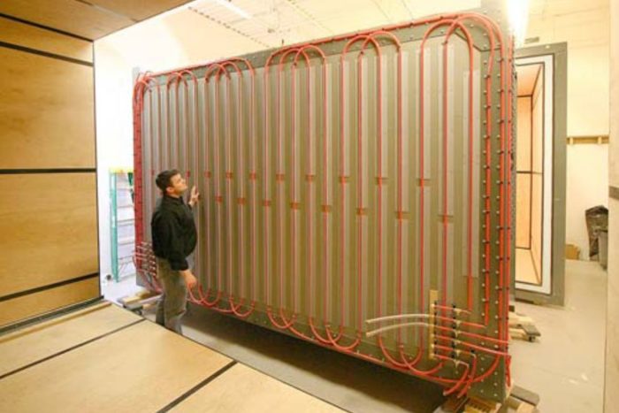
For the past five years, researchers at the Building Science Corporation (BSC) in Massachusetts have been testing the thermal performance of a variety of wall assemblies as part of an ambitious project to develop a new metric to replace R-value. (I last reported on the project in my August 2011 article, A Bold Attempt to Slay R-Value.)
BSC researchers recently released information on the multi-year project:
- On August 1, 2012, BSC principal Chris Schumacher gave a presentation, “Thermal Metric Project: A year of progress,” at the Westford Building Science Symposium.
- On August 6, 2012, BSC released a three-page report, “Thermal Metric Research Project.”
The BSC project is financed by a group of five insulation manufacturers and one trade organization — Dow, U.S. Greenfiber, Honeywell, Huntsman Polyurethanes, Icynene, and the North American Insulation Manufacturers Association — known collectively as the “Thermal Metric consortium.” While BSC hasn’t yet published a peer-reviewed paper reporting on their research project, the consortium has released enough details to draw a few conclusions.
Developing a new metric or label for wall assemblies
The BSC researchers set out to measure the rate of heat flow through a variety of wall assemblies under different conditions — for example, at different rates of air flow. The intent was to compare the performance of a wall when air was leaking through the wall with the performance of the wall without any air leakage. The researchers also hoped to test wall assemblies at different outdoor temperatures and to quantify the effect of thermal bridging.
Eventually, the BSC researchers hope to propose a new metric for wall assemblies — something akin to the NFRC label now found on windows. “The window industry was in disarray a decade and a half ago, and it was very difficult for practitioners to select windows,” said Joseph Lstiburek, a principle of BSC. “Then…
Weekly Newsletter
Get building science and energy efficiency advice, plus special offers, in your inbox.

This article is only available to GBA Prime Members
Sign up for a free trial and get instant access to this article as well as GBA’s complete library of premium articles and construction details.
Start Free TrialAlready a member? Log in


24 Comments
Good blog... but I'm curious
Great summary Martin. I can't wait till BSC comes up with the new metric for replacing the R-value system. I’m wondering why BSC is using 144°F outside temperature for testing… anyone building in Death Valley? Or is it the reflective sun light of a Low-e window heating on the neighbor’s walls?
Response to Armando Cobo
Armando,
When Joe Lstiburek originally announced his bold plan back in 2007, he said that he intended to test wall assemblies at temperatures ranging from -18°F to 144°F. Although these tests were eventually performed on sealed walls, the researchers scaled back the number of temperatures at which they tested the walls with air flow through the walls -- in part because the testing is expensive and time-consuming. At a 10 pascal pressure difference, the walls were tested at only two outdoor temperatures: 0°F and 108°F. I'll leave it to the insulation experts to judge whether the results of tests at these two temperatures are more or less meaningful than tests performed at more moderate temperatures.
Concerning your question about testing at 144°F: I think that it is certainly possible for an attic to get that hot.
When it comes to the upper temperature limits for walls, your reference to window reflections is appropriate. Researchers have measured siding temperatures as high as 219°F due to sunlight reflecting off a nearby window.
GBA doing what yaa all do
GBA doing what yaa all do best, AAA blog.
Ah, glorious data!
Great stuff, I know these tests take a lot to perform but I sure would like to see another assembly or two tested, particularly with a Blown in Blanket type application with a product like CertainTeed's Optima or other short fiber wall insulation dense packed and/or cellulose. Is this on ongoing study?
Response to Kyle Chase
Kyle,
Q. "Is this on ongoing study?"
A. Yes. The hope is to test more wall assembly types in the future.
Kyle, read again, damp spray
Kyle, read again, damp spray cellulose is wall 4, and basically is the test you are looking for.
As Earth quickly warms
Armando,
BSC is looking ahead, the 144 F is the cold climate version.
Martin makes a good point about high attic temperatures, I have recorded 130 F in Minneapolis. I would be interested in the dynamic between a 75 F conditioned space and a 130 F or more attic.
Counterintuitive, for me
Very interesting information. Thanks for this article. I wonder if anyone can help me understand a few items that are counterintuitive for me. For example, why is open-cell foam less affected by moving air than closed-cell foam? I would expect the opposite.
I also cannot visualize the "heat recovery" effect when infiltration or exfiltration happens through colander-sized holes. My thinking is that the delta-T across the wall assembly doesn't vary between the two scenarios, in that the indoor and outdoor temperatures are the same in both cases. If the same mass of air at the same temperature is moving from inside to outside, from where do we get the described energy usage differential, when we compare more small holes to fewer bigger ones? Heating the same mass of air by the same number of degrees from outside to inside should require the same number of BTUs.
The analogy to a heat exchanger seems off the mark. In a heat exchanger, intake air passes exhaust air in close proximity, so that heat can be exchanged between the counter-flowing streams. It sounds like in the test apparatus, and certainly in a home on a windy day, the flows are separated. Infiltration tends to occur on the windward side and the lower story, while exfiltration is greater on the leeward side and the upper story. There is no path for heat exchange between the incoming and exiting air streams, so far as I can see. What am I missing?
Response to Derek Roff
Derek,
Concerning the differences in performance between the walls with open-cell spray foam and closed-cell spray foam: I agree that some of the findings are hard to explain. It's hard to know, at this point, whether these differences will prove to be consistent (with other wall assemblies) or simply represent the "noise" in data with which every researcher is familiar.
The second bar graph ("As-Built with Imposed Air Flow") shows that the walls with open-cell foam had more air flow at high temperatures, but less air flow at low temperatures, than the walls with closed-cell foam.
The next graph ("Q Sealed vs. Q Imposed") showed that air leakage degraded the thermal performance of the closed-cell foam wall more than the open-cell foam wall -- a result that is, indeed, counterintuitive.
Here's an attempt to address your question about heat exchange.
First, let's talk about infiltration. If all the air leaks through one big hole, it basically enters the room at the outdoor temperature. In winter, the infiltrating air is cold.
If the infiltrating air comes through colander-sized holes, it filters through the insulation on the way in, and the air picks up some heat from the insulation fibers in the wall. By the time the air reaches the room, it has warmed up a little.
Now let's talk about the exfiltration scenario. The wall is losing heat by conduction. The outer layers of the insulation are cold; the inner layers of the insulation are warm. If the exfiltrating air leaves by one big hole, the exfiltrating air doesn't warm up the fibers of insulation in the wall.
However, if the exfiltrating air leaves through colander-sized holes, it has a chance to warm up the fibers of the insulation in the wall on the way out. This reduces the conductive heat loss through the wall.
ICF walls
I hope a future test includes an ICF wall panel
Spray foam counter-intuivity . . .
Excellent blog - thanks to both BSC and Martin/GBA for sharing and posters for your comments.
The spray foam performance issue is very topical for us right now. I wonder if the "counterintuitive' result for closed cell foam might have anything to do with the physical realities of the wall assembly. An R-13 layer of closed cell foam does not fill a 2x4 cavity (I'm assuming this part-filled cavity was the condition for the tested assembly??). Is it possible that the lack of alignment between insulation and air barrier on one large face of the stud bay resulted in increased heat loss, perhaps due to convection in the void between insulation and interior drywall? Accepting that even ccSPF allows some infiltration opens up further discussion about whether it is OK to only part fill a wall cavity with ccSPF? I was taught that insulation had to be in contact with air barrier on all 6 sides. Given how labor-intensive and wasteful it is to achieve this in a ccSPF install, I've been tempted to say OK to leaving the ccSPF fill just shy of the drywall plane of the cavity. But I'm wondering if this "counterintuitive" result hints to the contrary. Any thoughts? Alistair
Air tight?
Perhaps, someone should mention that brick built walls, with internal wet plaster finish.
Are airtight!
A possible move to more robust building?
Response to Alistair Jackson
Alistair,
You have proposed a possible explanation for the data reported by BSC researchers. I think, however, that we need more data before we can draw conclusions.
Certainly, R-13 closed-cell spray foam is a meager amount of insulation, and the effects seen by the researchers may be connected to the fact that they were testing low-R walls.
I don't think the effect has anything to do with whether or not the air barrier and the thermal barrier are properly aligned, however. As long as there are no air-leakage cracks between the spray foam and the framing members, this problem of alignment does not occur with spray foam -- because the foam is both an air barrier and a thermal barrier.
Response to Roger Anthony
Roger,
You're right that some wall assembly types (including load-bearing brick walls finished with plaster) have lower rates of air leakage than others (for example, a wood-framed wall insulated with fiberglass batts).
However, creating a good air barrier involves more than just choosing a method of wall construction. Most air leaks do not occur in the field of the wall -- they occur at seams and penetrations. That's why a house with brick walls can still be very leaky.
Any ideas about how dense
Any ideas about how dense pack fiberglass (blown in Spider) would compare to the tested assemblies?
Response to Rob Silbajoris
Rob,
There is no indication from BSC researchers that they have measured the performance of a wall insulated with blown-in fiberglass.
Perhaps that is one type of wall assembly that will be tested in the future.
Why no modeling?
This is a great project and a necessary step in the right direction. I agree that quantifying the performance of wall assemblies' acting factors, such as materials and geometry, is very important.
But I disagree with the process for making those determinations.
Why are they not taking this amazing data and calibrating CFD models? They are only testing 8 wall assemblies. With CFD the number of unique wall assemblies (and cost of performing the tests) would be vastly improved. Furthermore, the types of measurements would no longer be limited. Relying solely on physical testing is going to shut out possible innovation because of the huge cost involved in physically creating the data to generate the performance stickers. Invention will be hampered because when a sticker is required for validation, those assemblies not tested get left out. In order to reduce the cost of testing and to allow for more creativity in design, we have to start thinking about how software can enhance our scientific processes. Indeed it can! BSC needs to admit that modeling in software is the future! Physical testing and digital modeling can work together for deeper understanding.
Response to Robert Beach
[Note to GBA readers: "CFD models" = Computational Fluid Dynamics models]
Robert,
I don't think there is any evidence that BSC researchers would be averse to having their data used to improve existing computer models.
The first step is to make hot box measurements. The second step is to use the hot box data to improve existing models.
That is the path taken by those who developed the NFRC labels, and the BSC researchers appear to be using the NFRC path as a guide to their work. Virtually all NFRC values are now calculated with software, not direct measurements.
NFRC
The point about how NFRC primarily uses software for generating labels is good to know. But I counter your point that their data will improve models; it will calibrate/validate the models. I would say that the models improve/expand upon the tests, not the other way around. The two processes should be happening in parallel, with the primary focus on creating modeling processes. I believe that the Thermal Metric will be hampered by relying solely on physical testing to determine the label's logic. I admit I am making many assumptions about BSC's process and hopefully the peer-reviewed paper will shed light on how they plan on, or have been modeling these suckers.
Where are the SIPs?
I am curious why SIPs were not tested? Perhaps the comparison would not be apples to apples. Hopefully SIPs and ICFs are tested in the future - and maybe even compared to each other. I would like to see those results. Not sure how they would compare to the stud walls though - Prius vs. Durango???
Response to Thomas Moore
Thomas,
As far as I know, the reasons that BSC has only tested a limited number of wall assemblies, and has not yet tested a SIP wall, are the following:
1. It takes a long time to test a single wall assembly.
2. The testing is expensive, so researchers have to prioritize which assemblies to test.
3. The first wall assemblies tested were those that were of interest to the sponsors of the project (all insulation manufacturers).
Do you know if reflective
Do you know if reflective insulation is on the list to test? I would be interested to see where this product falls. http://www.ecofoil.com/All-Products/Double-Bubble-Insulation
Response to Brandi Borkgren
Brandi,
There's no need to test foil-faced bubble wrap more than it's already been tested.
I've written many articles on the topic; one of them was called Martin’s Useless Products List.
Here's what I wrote in that article: "Distributors of foil-faced bubble wrap 'insulation' have a rich history of exaggeration and fraud. A September 2003 exposé in Energy Design Update documented several wild exaggerations by manufacturers. Although foil-faced bubble wrap has an R-value of about 1 or perhaps 2, several manufacturers have falsely claimed R-values ranging from 5 to 10. In hopes of avoiding FTC enforcement action, the manufacturers, caught red-handed, sent EDU a comical cavalcade of apology letters. The bottom line: foil-faced bubble wrap costs just as much as — and in some cases much more than — 1-inch-thick rigid foam. As building scientist John Straube pointed out, 'I might recommend it if it were half the price of R-5 rigid foam, but if it costs more than R-5 foam then you have to be crazy or stupid to use it.' ”
RE: Robert Beach
Robert,
CFD and energy simulations are still not at the point where they can model everything we need to model. They have a hard time coupling mass flows with energy as well as difficultly with some forms of radiant transfer. Lawerence Berkeley National Labs (writers of EnergyPlus, eQuest, THERM) has a relatively new hot box project working on resolving some of these issues. The fact is that if you really want to get down to the exacting level described in the article the best way to do it currently is via physical modeling. That doesn't mean energy models are useless, nor that they will not be made better in the future. It does mean that for this pioneering type of work it seems the team is going for the hard slog leaving nothing to assumptions (or at least clear limitations) path.
I would love to see this with variable humidity as an added complexity.
Is the exterior XPS taped or sealed to the framing? If so I am blown away by the spray foam performance improvement over it. I would not haveexpected that.
Log in or become a member to post a comment.
Sign up Log in