
More Guest Blogs


This is the third of three posts on attic renovations developed by Byggmeister, a design-build remodeling company in Newton, Mass. The first two parts, written by Byggmeister CEO Rachel White, can be found here and here.
In many Boston area homes, it’s common that a homeowner at some point in the past has finished the attic to create more living space. In these conversions, there typically has been little to no air sealing, existing insulation has been poorly installed, and roof venting, if it exists at all, is ineffective. These spaces can be hard to heat, cool, and keep dry.
Byggmeister’s approach to renovating attics like this has been to remove the finishes from the sloped areas, insulate the underside of the roof with closed-cell spray foam, and install new finishes. This method has yielded great results, but it’s disruptive, expensive, and carbon-intensive.
A lower-cost and lower-carbon alternative would be to leave the finishes intact and to switch from spray foam to blown-in cellulose. But when we use an air-permeable insulation such as cellulose, the building code requires a vent space between the insulation and the roof sheathing. Retrofitting this space generally requires removing finishes—exactly what we’re hoping to avoid.
Wouldn’t it be nice if we could forego the ventilation space and just dense-pack the rafter cavity? As luck would have it, a team at Building Science Corp. (BSC) conducted a study on the unvented roof approach and recently published the results. The researchers observed that dense-packed cellulose in unvented roof assemblies sometimes caused the roof sheathing to become wet enough for long enough to lead to mold growth. However, these conditions occurred primarily at the highest points of the roof near the ridge.
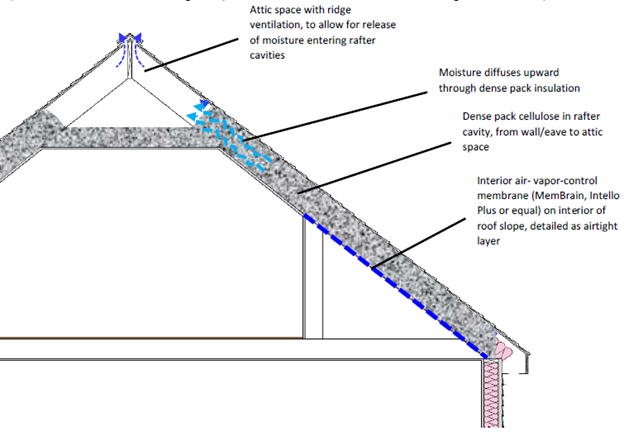
In a section titled “Further Work” they suggest that if there were an open attic with adequate venting above unvented roof slopes, as shown above, the additional drying potential might keep the area near the ridge dry enough to avoid trouble. They go on to cite many others who state that this “short slope” approach has been used by weatherization contractors in cold climates since the early ’90s without reported callback issues or observed moisture damage during inspections.
Putting theory into practice
We decided we wanted to try the “short slope” approach on a few projects and install some moisture monitoring equipment both to reassure our clients, ourselves, and skeptical building officials, and also to help create a data set in support of this method.
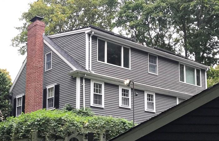
The first project where we tried this had several features that made it an interesting test case. The third floor was completely finished and featured a shed dormer across most of the backside. The roof had a 4:12 pitch and faced south with solar panels covering most of it, as the photo at the top of this post shows. The rest of the roof was closer to a 9:12 pitch and faced mostly north except for two short sections. It had a relatively new asphalt-shingle roof over board sheathing with no existing venting.
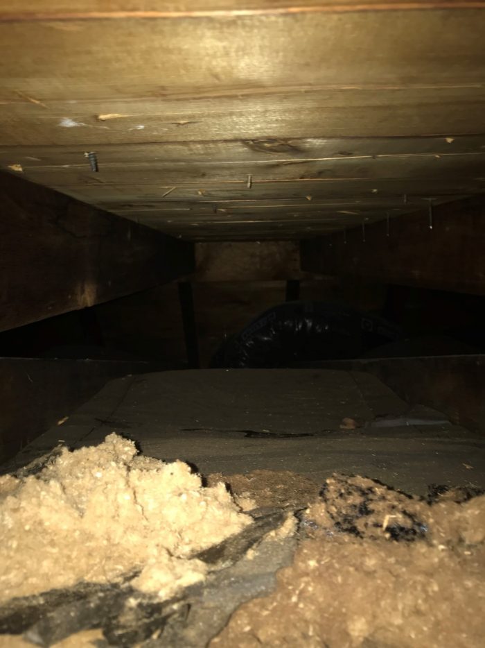
All the slopes were finished on the inside, but the view through a small access panel indicated that the only existing insulation was 1 in. of fiberglass batts on top of the ceiling, as shown in the photo at right.
Our prior approach—removing all the ceiling finishes, insulating with low-GWP closed cell spray foam, and installing new finishes—would have generated approximately 3,000 kilograms of CO2equivalent and would have cost a lot of money. We estimate that our new approach—leaving the finishes in place and switching to cellulose—reduced the embodied carbon impact to around minus 1,000 (yes, a negative carbon impact) while cutting the cost by almost 50%. The substantial decrease in upfront carbon emissions combined with the nearly as substantial cost savings seemed to make this a no-brainer, but first we had to take a hard look at the risks.
We knew it would be important to achieve good cellulose density because the resilience of the assembly relies on minimal airflow through the insulation and full contact with the roof sheathing. The ideal density target is around 4 lbs. per cubic foot. To monitor density we asked our cellulose installer to pack the sloped areas first and count how many bags of cellulose they used. We estimated the volume of the cavity space we were insulating and, using the pounds of cellulose per bag, calculated an installed density of around 3.8 lbs/ft3 —not too bad.
Where the insulation was blown into 2×6 rafter bays, the R-value was roughly 21 after we completed our work. In the attic area, we were able to install as much as 16 inches of cellulose for an R-value of about 60.
We installed just over a dozen monitoring devices to record temperature, humidity, and the percent moisture content of the roof sheathing in a variety of locations. We use the Omnisense S-1, S-11, and S-2 sensors. They come with lithium batteries with an expected life of 15 or more years; we anticipate monitoring these assemblies for two or three years.
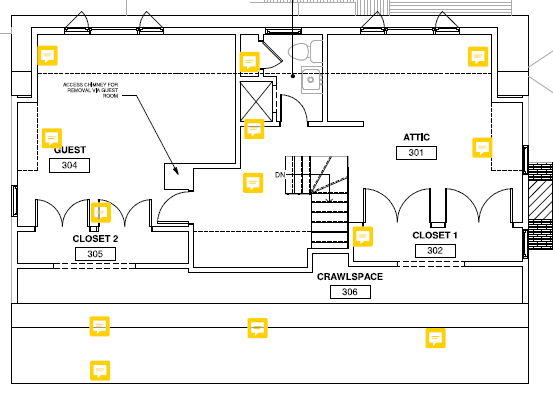
The yellow comment boxes in the illustration above show all the locations of monitors. The illustration below shows where in the assembly they were located.
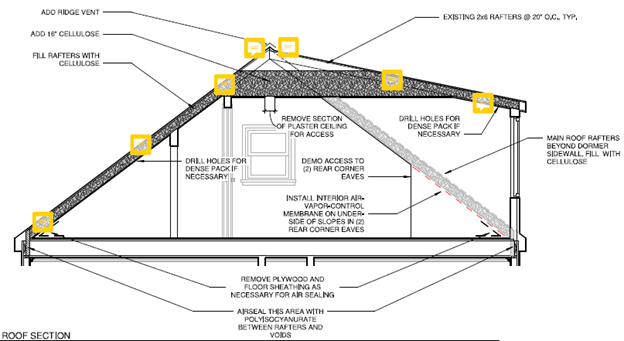
The installation was completed toward the end of 2020. So far, the data show that only the roof sheathing above the loose blown cellulose near the new ridge vent appears to be reaching a moisture content above 15%. The monitors in that area hovered around 20% between January and March with only a couple spikes just over 25%, always dropping back towards 20% in a day or two. In March, all monitors dropped below 15% and most have been in single digits ever since. These initial results seem very consistent with the BSC research indicating that moisture accumulates near the ridge in the colder months but dries out quickly in the spring.
More projects in the works
We are now completing our third project using this strategy and are due to start a fourth this autumn. We are continuing to install monitors, principally in those areas that are unique to each project and that might be at a higher risk for moisture accumulation, such as dormers with no venting of their own and little to no connection to the main vented attic space. We’ve also installed a few monitors in dense-packed slopes between soffits and vertical dormer walls to see if lack of connection to the attic above could lead to moisture accumulation there.
A big concern of ours going into this was push-back from building inspectors based on the lack of code-compliant venting. On our first two projects we provided an architect-stamped letter when we applied for the building permit, requesting approval of the approach under MA 780 CMR:104.11 Alternative Materials, Design, and Methods of Construction. On our third project we didn’t provide a stamped letter at permit application but are prepared to provide one if the inspectors aren’t comfortable with our explanation and monitoring strategy.
We are hopeful that the data from our monitoring will show that these assemblies are staying dry enough for us to continue choosing cellulose over spray foam in finished attic retrofits. Once we have a few more seasons of data from our handful of projects, we plan to share the results with our colleagues and see where that takes us.
Brendan Kavanagh is project manager and performance manager at Byggmeister.
Weekly Newsletter
Get building science and energy efficiency advice, plus special offers, in your inbox.


22 Comments
Nice work. As it should be, code is conservative and in some designs and with care (like great air sealing and modest interior humidity), non-code designs can work.
I suspect that Intello does better in this application - better moisture performance and more durable as an air barrier. Vapor retarder paint is used on the upper portion of the wall?
> roof sheathing above the loose blown cellulose near the new ridge vent ... spikes just over 25%
Would a little (like 100 CFM) balanced or positive pressure, humidistat controlled, powered ventilation of the mini-attic eliminate this?
There isn't an open cell pump-in foam that would be code compliant (because it would be an air barrier)?
I was thinking about powered ventilation too. With an ECM fan, it could have very low energy consumption, especially with variable speed control instead of cycling to stay below the RH setpoint, but maybe with more sophisticated controls to make sure the outdoor dew point is lower than indoor before turning the fan on so you can be confident it's actually helping. Positive pressure could actually counteract stack effect leakage, rather than amplifying it, in the winter, but you might want to reverse that for the summer, or just use balanced fans all year.
That's the right thought process. But while we use fans everywhere else, some marginal results with 1000+ CFM attic exhaust fans got distorted into "all attic fans are bad".
Jon & Charlie, So far I'm not too worried about a brief spike that dries out quickly. If I start to see longer periods of high moisture content, maybe a fan of some kind could be a good way to alleviate the issue quickly. Wouldn't it be nice if we didn't need any fans with sophisticated controls?
Jon, our goal was to use cellulose instead of spray foam so we didn't consider any open cell options. Also, I'm not sure I understand your question on the vapor retarder paint on the walls. Since our work is in existing homes we are trying to maintain as much of the finish material as possible and only paint where necessary.
You use a vapor retarder membrane on the lower part of the slope (dark blue). What limits moisture entering in the upper part of the slope (light blue)? Vapor retarder paint would be a low impact option that would reduce the amount of moisture that needs to be removed by the diffusion port/attic.
Overall, I think it's an important question - can large diffusion ports (aka mini-attics) plus other options (like taped Intello) make non-vented, cellulose filled cathedral roofs reliably work in Z4+ climates?
Ah OK, yes we used latex paint on the ceilings in this project but more because we needed to paint the ceilings anyways and not as a design component of this assembly. That said I do think it will help and provided some paint scope works for the project it would definitely be a good idea to include it.
Thanks for your feedback Jon!
How does this relate to a vapor diffusion port as used in CZ 1-3? I can't tell from the article if the ridge vent is air-flow open or if it has a vapor open but air-tight membrane? I'm guessing it doesn't (as testing the vapor diffusion port approach was the point of the linked paper). Or maybe that's the point, the air-space under the diffusion port changes the situation somehow?
If it doesn't then this is a vented mini-attic but without soffit vents? So the moisture is leaving via air-exchange through the ridge vent?
[How does this relate to a vapor diffusion port as used in CZ 1-3? I]
In those cases the insulation goes all the way up to the ridge of the roof however obviously with an attic truss system you can't run the insulation up to the ridge. I don't think in the humidity of CZ1-3 you would want this type of insulating system because there isn't enough air moving up and out the ridge. It's why as the author stated the typical approach is to create vent channel between the insulation and the roof deck leading from the soffits to the ridge.
Hi James, sorry for the delayed response. For the most part it's the latter, a vented mini-attic without soffit vents sums it up nicely. In our first project (the one I provided the most detail on) there was only the open ridge vent above a very tight attic space and no gable vents. In our 2nd project the attic space was much larger with existing ridge and gable vents. In our 3rd project the attic space was in between the first 2 in size and there were existing gable vents. On this 3rd project we installed an air tight but very vapor open membrane beneath the ridge because we were re-roofing anyways. I'll be curious to see if that + the gable vents will allow for enough drying through this coming winter, if not we will likely cut the membrane out for an air-open ridge vent.
The vapor diffusion ports as used in CZ 1-3 appeared to not allow for enough drying potential to be considered safe enough for our CZ 5. We are trying to determine whether similar approaches with more drying potential in the right areas could be enough to be considered safe in our colder climates.
Can this technique be done if the kneewall is already filled with 2ft cellulose with polyiso on the kneewalls? Thus, fill the ceiling with cellulose but stop at the kneewall which has already been blocked with polyiso?
Whoever did our cathedral ceilings added R13 batts in the sloping ceiling section and shotty insulation (not fully covering) in the top mini attic. Do you remove the batts prior to starting or blow and compress the batts down? Another question, if there is poor insulation in the top mini attic, can there cellulose blown into just that section?
Hi Will,
We had a situation similar to what you're describing in our 2nd project. We decided to leave all the existing insulation in place and only air seal/add insulation to minimize the carbon impact of the work. I'm not sure it that was the right call because it made our air sealer's work much more challenging, but I have a lot of confidence in him and his blower door guided air sealing practices. Then we did our best to dense pack the slopes which already had some very patching fiberglass and cellulose in them, and topped off the attic with loose blown.
You want to be sure you're getting your ceiling as air tight as you can, this will lessen the amount of moisture getting into the attic in winter. If you don't have someone who can do effective air sealing with the insulation in place, I'd suggest removing it at least from the attic. In the slopes I'd say if you can get the batts out without too much effort I would, otherwise leave them and pack them down.
All-in-all we are still testing this approach out so I wouldn't say definitively yes you can or no you cant. That said I do feel fairly confident in this strategy so far and it seems like it might work in your situation.
This is awesome. These type of retrofits are brutal. If field data like this can also show a minimal risk for this technique, it could save a lot of labor in a lot of homes.
Thank you for the article. Do you see the R21 roof being an issue with the various local inspectors in Eastern MA?
Since we are just filling existing cavities that meets the code requirements for renovation. If you're in a full gut reno or new construction I don't think they'd be OK with it.
Is there any updated data on this approach?
I'm looking to retrofit our finished attic space.
It's a hip roof with gabled dormers on all four sides located in Indianapolis. My first thought has been to just fully refinish the space with either rigid foam in the slopes roof or spray foam.
The approach in the article interests me though, so I'm interested in updated data.
Thanks!
Max
Hey max,
The data so far shows the roofs seem to be performing reasonably well. That said a hipped roof has severely limited potential for ridge venting and likely no gable vents either. Unless the dormer attics are open to the main attic space and you can get a good amount of venting up there, I’d be cautious going with a strategy like this.
Thanks for the reply!
So it's actually a hipped roof with a flat top(a mansard?).
Does this change the concerns for the strategy?
Hi Max, sorry for the delay.
Yes a flat top would essential render the concepts in this strategy useless, unless you can come up with a clever way to add venting that I haven't seen. If you haven't done this work yet and are thinking about a "cut & cobble" rigid foam between the rafters approach I'd look around for recycled foam board either from a supplier or I've heard folks have had some success on Craigslist or Facebook marketplace. If you're leaning towards spray foam just make sure you use a closed cell foam with an HFO blowing agent for the reduced global warming impact.
Good luck!
Is there a reason you installed a membrain in the dark blue section of the roof in line with the rafters? instead of lining it up with the knee wall and then the airtight layer on the second floor? More of a zigzig than a straight along the diagonal of the rafters?
We are in a similar situation and trying to decide the easiest to build option. Reaching all the way down into the corners of the eaves seems difficult versus working closer to the knee walls and ceiling of the second floor?
Edit: read your post#2 and you mentioned the transitions in planes leads to headaches in the sealing at each transition. From a constructability standpoint, do you think the transitions in planes is harder than doing under-rafter membrane all the way into the eave bottoms?
guillow,
You may find this article interesting: https://www.greenbuildingadvisor.com/article/insulating-behind-kneewalls
Also, hoping to clarify, in the drawing, are the soffit vents connected into the rafter bays still somehow? or are the rafter bays fully sealed on 5 sides (only opening is at the very top into the mini-attic vented space)? Do you have airtight blocking at the bottom of the rafter back with polyiso?
If so, was this a compromise or a conscious decision to block it off? Would it be better to have soffit vents connect to the dense packed rafter sloped sections to allow for some air flow through the cellulose up to the attic? Or would it only introduce more moisture into the cellulose in the summer?
guillow,
Cellulose is pretty resistant to wind-washing. I doubt you would get (or want) any air movement through it.
Log in or create an account to post a comment.
Sign up Log in