

More Building Science


As we continue our study of indoor air quality and filtration, we now come back to duct design. Today’s lesson is on an interesting bit of physics that applies to anything that flows. It could be heat or particles or electromagnetic energy. In our case, it’s air — a fluid — and the physics we’re looking at is called the continuity equation.
It’s basically a conservation law, similar to conservation of energy. I’ll use diagrams to tell the story.
The basic continuity
First, we have a duct. Air enters the duct from the left. As the air moves through the duct, it encounters a reducer and then a smaller duct.

What do we know about the flow here? Thinking about conservation laws, we can safely assume that all of the air that enters the duct on the left has to come out of the duct somewhere. We’ll take the case of the perfectly sealed duct — so no air leaks out along the way.
But we can strengthen our statement from just the amount of air to the rate of flow. Using “those annoying imperial units,” we can say that for each cubic foot per minute (cfm) of air entering the duct on the left, a matching cfm of air leaves the duct on the right. We represent flow here by the symbol q.
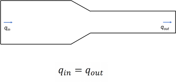
So, we have conservation of air — no air is created or destroyed in the duct — and we have conservation of the flow rate. The rate of flow entering equals the rate of flow leaving. But to make this second claim we’ve had to make an assumption.
We know the number of air molecules has to be the same no matter what, but to say the volume of air is the same means that the density doesn’t change. We’re assuming that air is incompressible when we say that. Is it true? Can we legitimately say air is an incompressible fluid?
The general answer to the question of incompressibility, as you know, is that air is certainly a compressible fluid. But we can treat it as incompressible in duct systems because the pressure changes it goes through are small enough the density of the air doesn’t change.
And that’s why our statement above, that the flow rate (in cubic feet per minute) of air entering the duct is equal to the flow rate of air leaving the duct. We have continuity!
But what happens to the velocity?
Air velocity in ducts is a really critical factor in how well ducts do their job of efficiently and quietly moving the right amount of air from one place to another. We’ll explore that topic further in a future article, but for now, let’s nail down what happens to the velocity as air goes from a larger to a smaller duct.
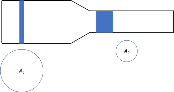
First, going back to our statement about equal flow rates, let’s look at equal volumes of air moving through the duct system. Let’s say the narrow blue strip in the larger duct represents one cubic foot of air. I’ve shown the cross section of the duct, A1, below that strip.
In the smaller duct, that same cubic foot of air is spread out over a greater length because the cross section, A2, is smaller. Makes sense, right? You get equal volumes because the volume in each case is the cross-sectional area times the length.
The next step is understanding what those different lengths mean for the velocity. According to our equation for the flow rates, qin = qout, in the same time that whole narrow plug of air on the left will move forward by one length, the wider plug of air on the right will also move forward by one length.
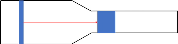
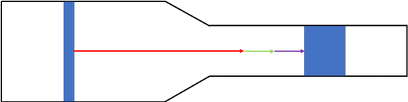
Like this:
The red arrow shows the initial distance between the two plugs of air. As you can see, the distance between increased.
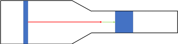
In the next time block, the narrow plug advances one more of its lengths. The fat plug likewise moves forward by one of its lengths.
And then again.
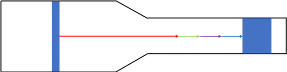
Each time the air advances by one cubic foot, the air in the smaller duct moves farther than the air in the larger duct. In other words, the velocity in the smaller duct is higher than that in the larger duct. And it’s related to the cross-sectional area.
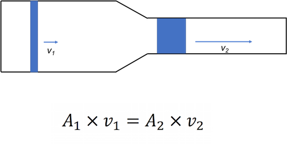
That equation for area and velocity is called the continuity equation for incompressible fluids.
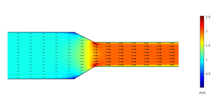
Steven Doggett, PhD, LEED AP, ran a computational fluid dynamics (CFD) simulation using the geometry of my diagrams above and came up with some nice images of the velocity field. Here’s the first one, simulated for laminar flow:
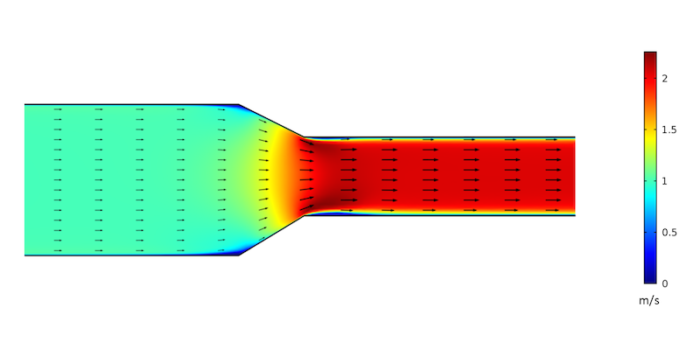
It’s interesting to see how the velocity changes in the reducer fitting. One thing to note is that this simulation assumed laminar flow whereas in real ducts there would be some turbulence. And because you’re now wondering, here is his simulation of the same thing, with turbulence:
A little bit slower. A little more action at the corners. A little flatter at the reduction. Overall, pretty similar and both really interesting to look at.
The key takeaway here is that air moves from a larger to a smaller duct, the velocity increases. When it moves from a smaller to a larger duct, the velocity decreases. In both cases, the flow rate — the amount of air moving through the duct, in cubic feet per minute — stays the same.
Applications of the continuity equation
Since we’ve just looked at problems with filtering the air in my last article, you may suspect that this has some relation. And you’re right. A lot of filters cause problems with air flow because of excessive pressure drop. To solve the problem, you have to understand the relation between filter area, face velocity, and pressure drop. The continuity equation is involved. I’ll be going deeper into this with a couple of articles coming out soon.
The continuity equation is also critical in keeping the velocity in the ducts where you want it. If it goes too high, you get too much pressure drop and possibly noise.
And then there’s the issue of shooting conditioned air into rooms at the proper velocity to get enough mixing of the room air. That’s similar to the filter issue where you have to look at manufacturer’s specifications for supply registers except that you’re not trying to minimize pressure drop as with filters. You’re trying to pick the right register for the amount of air flow to get the right amount of throw and spread.
The topic in my first semester of introductory physics that I enjoyed the most was hydrodynamics, the study of fluids in motion. We didn’t get into viscosity, but we did learn about Bernoulli’s equation, Venturi tubes, and fluid velocity. I had no idea at the time that I’d be using this stuff in the real world nearly four decades later.
Of course, back in 1980 I wasn’t even able to predict that I’d be a baker in St. Louis in 1984, cleaning windows in Seattle in 1986, or teaching physics at Tarpon Springs High School in Florida in 1989. As Niels Bohr may have said, “It is difficult to predict, especially the future.”
Allison Bailes of Decatur, Georgia, is a speaker, writer, building science consultant, and the author of the Energy Vanguard Blog. You can follow him on Twitter at @EnergyVanguard.
Weekly Newsletter
Get building science and energy efficiency advice, plus special offers, in your inbox.


One Comment
I don't know about Bohr's alleged comment, but British mathematician Sir Horace Lamb (look him up) actually commented about fluid dynamics in his later years. In a 1932 speech he said "I am an old man now, and when I die and go to heaven, there are two matters on which I hope for enlightenment. One is quantum electrodynamics, and the other is the turbulent motion of fluids. And about the former I am rather optimistic." I would tend to agree. Fluid Mechanics was not my favorite college course, but I do look forward the articles still to come from Dr Bailes.
Log in or create an account to post a comment.
Sign up Log in