

More Energy-Smart Details


Transition points in a building assembly are critical locations to get right. They include foundation to above-grade walls, and above-grade walls to roof. It is at these junctures that the continuity of the four control layers is most subject to failure.
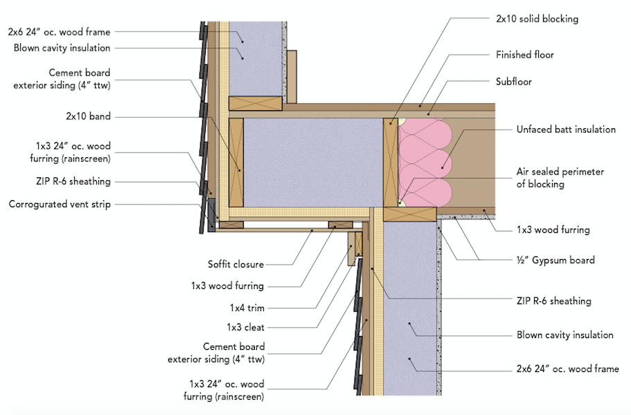
This detail shows the transition from the above-grade wall to the roof/ceiling assembly of a home designed to meet Passive House standards. The wall is framed with 2x6s, 24 in. o.c. and is insulated with 4 in. of polyisocyanurate rigid insulation on the exterior. The roof/cathedral ceiling was built with scissor trusses and includes venting through the eaves.
Bulk water is handled with a 2-ft. eave overhang, which will keep a large portion of the wall relatively dry in a typical rain event. (The overhang-to-head ratio is 2:1.) The wall has a 1×3 wood-furring rainscreen on the exterior to assist with drying. Note the drainage outlet/air inlet at the head trim. The exterior is 1×4 open-board siding, the upper edges of which are sloped 10 degrees to the exterior to move water away from the wall.
The exterior air barrier for the wall system is Zip sheathing, which also provides adequate shear strength in this coastal zone. (It is always a “plus” for a single material to perform multiple duties.) The drywall is the interior air barrier for the sloped ceiling. The challenge here is the transition from the wall to the interior drywall. A strip of self-adhered membrane connects the face of the exterior sheathing to the backside of the 3/4-in. plywood. While this may look difficult to construct, it’s not. The wall is framed and sheathed, the plywood is temporarily tacked to the top of the wall, the adhered membrane is installed and rolled, the trusses are installed, and the plywood is nailed off. The drywall, installed on…
Weekly Newsletter
Get building science and energy efficiency advice, plus special offers, in your inbox.

This article is only available to GBA Prime Members
Sign up for a free trial and get instant access to this article as well as GBA’s complete library of premium articles and construction details.
Start Free TrialAlready a member? Log in


2 Comments
A couple questions:
1. I don't understand where the spray foam (top plate to underside of roof vent) ends. (At first I thought the plan showed the spray foam extended all the way across the roof!) Some barrier (not labeled) runs between the polyiso exterior insulation, to the roof vent channel, to begin installing spray foam? Or if installed from the exterior, some barrier not shown in diagram, further to the interior. Not sure of the thickness installed before blown-in cellulose insulation begins, perhaps TBD by installer/builder. (In similar designs I thought a polyiso or ply barrier could be installed above and parallel to the wall, and between the trusses, no spray foam.)
2. When you get away from the wall, farther up the ceiling (towards the peak), how would you keep a consistent depth of blown-in insulation (drywall ceiling to vented airspace becomes too deep)? Cellulose might settle too low at peak and get blown too thick away from peak, in a vented roof? I was thinking Tyvek or similar tacked from truss to truss to limit depth at some point midway between exterior wall and peak. One neighbor had a problem with loose fill insulation drifting.
It seems like the placement of the Simpson truss ties will penetrate the continuous membrane over the top of the wall? Is this right? I assume they would have to be installed after the 3/4" plywood is nailed off on the trusses (then make a cut in the membrane, and seal around each truss tie).
Log in or become a member to post a comment.
Sign up Log in