

More Guest Blogs


Editor’s Note: This post is one of a series by Chris Stratton and Wen Lee, a husband-and-wife team living in the Los Angeles area who are turning their 1963 suburban house into an all-electric, zero-net energy home. They chronicle their attempts at a low-carbon, low-cost, and joyful lifestyle on their blog Frugal Happy. This post was written by Chris.
Almost every change we’ve made to the house is intended to decrease its energy consumption, but we made one big move that would increase consumption, all else being equal: We vaulted the ceiling. Raising the ceiling in the common area (kitchen, entry, dining area, and living room) is about aesthetics and how it feels to be in the space.
I knew it would be a huge change with lots of implications, but I sensed — hoped — it would completely transform the main living area of the house. (See the first image in the gallery above.)
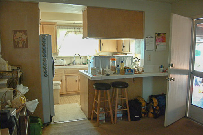
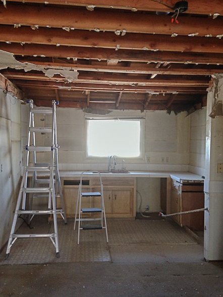
Before the renovation, the common area had a horizontal 8-foot popcorn ceiling. The dining area had no daylight and to me the ceiling felt low and oppressive. There were cabinets blocking the light from the single kitchen window to the west and inexplicable half-walls with latticed screens blocking the light from the windows and sliding glass doors in the living room to the east (see Image #2 in the gallery).
Removing these obstructions between the rooms and vaulting the ceiling to be parallel to the roof would open up and connect all these spaces together. Adding a skylight would bring more daylight to the dining area.
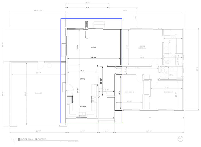
To envision what the space would look like with a vaulted ceiling and a skylight, I used the SketchUp model that I created to generate the floor plans. I made 3D interior views and tweaked the configuration to get a sense of the options I had. SketchUp does have daylighting functionality, but it’s not great. To get a better sense of what the daylighting would actually look like at different times of the day and year, I exported the SketchUp model and uploaded it into a daylight simulator called Daylight Visualizer (available free from the Danish skylight manufacturer Velux).
This application allowed me to generate still images and even animations of the space, and helped me with the placement and the sizing of the skylight. One thing I learned: a little skylight goes a long way.
Rebuilding the roof framing
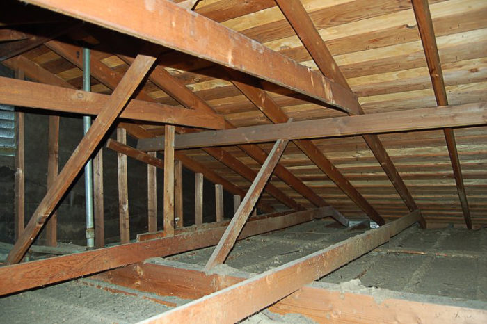
Vaulting the ceiling would require completely changing the roof structure in this part of the house (see Image #3 in the gallery). Pretty much everything you see in the photo (excluding the rafters) had to be removed.
The structure included purlins than ran mid-span below the rafters, supporting them. The horizontal span from the ridge (the spine of the roof, where the rafters meet) to the exterior bearing walls is about 15 feet — too long for the 2×6 rafters to span by themselves.
The purlins supported the rafters mid-span, turning that 15-foot span into two 7 1/2-foot spans that the 2×6 rafters can handle. These purlins are themselves carried by short, interspersed supports that extend roughly perpendicular to the slope of the roof. The supports, in turn, rest on a bearing wall or another structural member. In the living room, because the space was open and the purlins had no bearing wall, they rested instead on a massive 20-foot 6×13 solid Douglas fir beam that spanned the distance between two bearing walls.
The purlins, their supports, and all the ceiling joists would need to be removed in order to vault the ceiling, and all the loads that they carried would have to be transferred from the roof down to the ground in some other way.
I had some ideas for how to do this, but I did not know if these ideas were any good; I needed help from a structural engineer. The challenge with finding a structural engineer is that this is such a small residential project, and the architect is also the homeowner and doesn’t really know what he’s doing, so there would need to be a fair amount of hand-holding. I needed to find someone who was competent and reliable, but who would also be amenable to working with a novice architect.
I found a few helpful resources while trying to understand exactly what I was getting myself into. One was a post from another DIY home renovation blog, although they didn’t actually DIY the vaulting part. Another was a Fine Homebuilding article from 2007 called Ceiling Remodel: From Flat to Cathedral, written my Mike Guertin. (The article is behind a paywall — sorry). It gave me a sense of what the demolished ceiling would look like, what some of the structural options and considerations are, advice for fabricating vent/insulation combo out of rigid foam, as well as guidance on hiring a structural engineer. In our case, the engineer was definitely necessary.
Finding a structural engineer
I searched for local engineers online and looked at reviews, then contacted a local firm to schedule an appointment. I arrived at the meeting with drawings and some anxiety. I attempted to explain the project and when I handed the engineer my drawings, he grimaced. “What is this?” he exclaimed (paraphrased). “This is a mess. Why did you include every stud?” and so on.
The conversation didn’t go well and was kind of embarrassing, but it was a learning experience. The engineer conveyed that he was feeling put out, but still made an effort to make sense of what we were trying to do. He took one of my floor plans and drew on it by hand, giving a rough outline of the solution he had in mind, along with a quote for a full set of permit drawings. The price would be lower if I would go to the permitting office myself.
This all seemed reasonable, but I thought I would get another bid just to get a sense of the range of options and to feel like I was doing due diligence. Also, although the engineer’s disdain was not entirely unmerited, I wasn’t convinced that he was the guiding hand I was looking for.
I found another engineer who agreed to come out to the house. This second engineer was more easy-going and supportive of my DIY approach. He cautioned that this was a substantial project that I was undertaking, and wanted to make sure I was up for it. He offered to give guidance if I had questions even after his drawings were done and the permit issued, and his price was reasonable (around $1,500). I know that it’s best practice to get at least three bids, but I felt comfortable with this second engineer and decided to move forward with him.
Looking back now, I still think hiring him was a good decision. There were times when his drawings had missing details or sections that were just boilerplate images from other projects that didn’t actually match my project (!). This was a little concerning and annoying, but his load calculations seemed thorough and the details for the key structural details — structural member specs and spacing, brackets specs, fastener spacing, etc. — were good enough.
I brought the structural and architectural drawings to my local city’s permitting office, and after a couple rounds of feedback and revision, they were approved.
Plans call for a structural ridge
The new structure for the vaulted ceiling would entail a 4×12 structural ridge beam. The existing ridge board merely tied the rafters together — it didn’t actually support the roof. This new ridge beam would carry the weight of the roof, and would be installed below the ridge board. New 2×12 rafters would be attached to the sides of (“sistered” to) the existing 2×6 rafters.
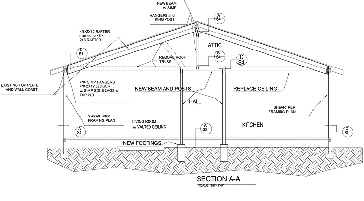
These new rafters would have to be notched to rest on the new ridge beam, and would be attached to the ridge beam and board with special structural brackets and an incredible quantity of nails. On the other end they would be supported on the bearing wall via a ledger board — basically a 2×8 attached to the top part of the wall. The new rafters would have to be notched to rest partially on the top plate while joist hangers would support them from below. The ridge beam itself would be supported by three posts — one at each end and one mid-span.
Each post is 4×4 inches. It’s amazing how much axial load wood can take. Three measly 4×4 posts can support the entire roof for that side of the house?!? (Yes, apparently.)
These posts have to take the load of the roof to the ground. The post on the northern end of the house is straightforward. It’s embedded in the exterior wall and can extend straight from the ridge beam to the bottom plate of the wall which is in turn supported by the concrete stem wall. The other two posts are directly above the hallway, and their load has to be distributed by beams that in turn are supported by posts at each end. These four posts would go through the floor and rest directly on brackets embedded in 18″ x 18″ x 18″ concrete footings poured in the crawlspace for this very purpose. Sounds like fun, eh?
Let’s dig in
After getting our permit, demolition could begin. The first step was to remove both the drywall and the structural members of the existing ceiling. Removing the drywall was fairly straightforward but extremely messy. I had already sent off a sample of the popcorn ceiling to be checked for asbestos, and it came back negative.
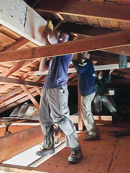
After the several hundred pounds of ceiling drywall was hauled away, the ceiling joists were exposed and we could begin removing them. But I wanted to sequence the removal of the structural members in order to maintain the building’s integrity during the construction process (see Image #4 in the gallery).
I decided to hire professional help for this next stage of the project. Changing the roof structure of the house is something that absolutely needed to be done correctly; the implications of screwing this part up would be both expensive and potentially dangerous.
I hired local contractors Michael and Christian to help me (or, more accurately, to let me help them) remove the existing roof structure and install the new one. As with the engineer, I needed to find a professional contractor who was okay working with an amateur (who also happened to be the client).
My role as both newbie construction grunt and client would inevitably make for some awkward moments. I came to appreciate Michael’s and Christian’s understanding, willingness to teach, dogged persistence, and good humor.
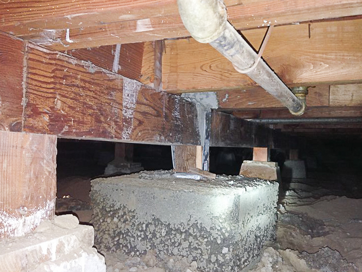
The first task at hand was to pour the footings for the new posts. This entailed going down into the crawlspace and digging holes where the new footings would be poured. It proved to be a Herculean task.
The clearance in the crawlspace between the bottom of the floor joists (spaced 16 inches-on-center) and the ground is about 18 inches. Supporting these floor joists every 6 feet are 4×6 girders, and the clearance under these girders is about 12 or so inches, depending on the ground in that area — barely enough room for a fit adult male to squeeze through. These girders are supported every 6 feet by short 4×4 posts that rest upon pyramidal concrete footings. Some of these footings were on small concrete slabs.
In order to make enough room to build the wooden form work to create the four new 18″ x 18″ x 18″ footings, some of these footings had to be moved, and the small (???) concrete slabs below them broken up into chunks using rotary drills and eventually a 35-lb demolition hammer. A 35-lb demolition hammer… the kind of thing that’s exhausting and awkward and unpleasant to use above ground for any amount of time.
Now, imagine using that thing to break up concrete in an 18-inch-high crawl space for eight hours. That’s what Christian and Michael did, with a little bit of help from me. Eventually we got the old concrete removed, the holes for the new footings excavated, and the formwork built.
Pouring the new pads
Michael picked up a trailer full of concrete and we were on our way. We took turns filling up 5-gallon buckets with wet concrete, hefting them into the house, and pouring them through the holes in the floor and into the forms below. This is probably self-evident, but it’s worth saying explicitly — concrete is heavy. A full 5-gallon bucket of concrete weighs about 100 pounds, and sometimes we were carrying two at a time.
The next day they came back and we took off the forms to reveal the footings. They were intact and massive. Mercifully the footings were now done and we could resume our work above ground. We removed the existing ceiling joists in preparation for installing the ridge beam.
We installed the secondary posts and beams to support the ridge beam. Once the three support posts were in place, we installed temporary supports to allow us to maneuver the giant ridge beam into its eventual permanent home.
And now, the ridge beam itself. The three of us were able to lift the ridge beam up onto a platform we built. The 20-foot ridge beam weighed 300 lb. or so. I thought we were going to lift it up on to the platform mechanically with some kind of winch, but no winch ever materialized. Christian seemed to think the three of us could just lift it up the 8 feet onto the platform. I was skeptical. But somehow we did it. Personally, if I were to do this again, I’d use a mechanical pulley of some kind (see Image #5 in the gallery).
The ridge beam is made up of thin sheets of wood all glued together, like a giant, thick piece of plywood. This type of manufactured wood product — called laminated veneer lumber (LVL) — is very strong and dimensionally stable, and making it doesn’t require cutting down huge old trees. LVL and another engineered wood product — cross-laminated timber (CLT) — are even beginning to be used in mid-rise buildings instead of steel in some places. Steel production is extremely energy-intensive and creates a huge amount of carbon dioxide pollution, even when it’s recycled.
Eventually we got the new ridge beam into its final position. We installed temporary supports to hold the ridge beam in place while we prepared the permanent supports.
Adding new rafters: Not easy in a tight space
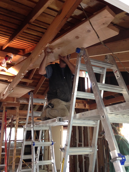
Once the new ridge beam was in place, we could begin installing the new 2×12 rafters. These rafters were almost as long as the ridge beam itself, and they would all need to be cut one by one and fit into place.
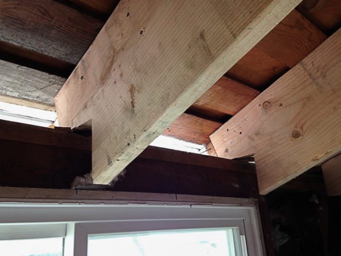
Christian notched the end of each new rafter to fit snugly against both the old ridge board and the new ridge beam (see Image #6 in the gallery).
I learned that it is difficult to install new rafters in an existing roof. There is very little clearance to get the new member into position. We had to knock out all of the blocking between the existing rafters in order to have enough space to insert the new 2x12s — and even then it was difficult. The new rafters were long and heavy and not always straight. It was definitely a strong two-person job, and some kind of platform or scaffolding is a must.
The “birdsmouth” cut that rested on the bearing wall was complicated by my, well, complicated design for the wall assembly. The top half of the rafter would rest on the bearing wall, but the bottom half would be carried by a joist hanger attached to a ledger board attached to the bearing wall. But (!) the ledger board couldn’t go on until the wall was insulated and strengthened with interior plywood.
In the interim, the new rafter would be supported only by the top half resting on the bearing wall. This was not ideal because only half the rafter is supported (effectively it’s another 2×6 rafter) and it makes the rafters prone to splitting at the notch (see Image #7 in the gallery).
It was the best solution I could come up with at the time, and fortunately it eventually worked out as planned, albeit with a nervous-making, nail-biting interim. This is the kind of detailed, 4th-dimensional task sequencing that’s hard to anticipate in the abstract beforehand in the design and planning stages, especially when you’re doing something unconventional and/or are inexperienced like me.
Eventually we got all the brackets installed and the new vaulted roof structure was complete! I’m very glad that I had Christian and Michael to guide me through the process.
Vaulting the ceiling was a significant undertaking, but it has completely transformed the space, as I hoped it would. What used to feel dark and cloistered is now airy and open. The change has been so significant, it’s hard to believe it’s the same house. Seeing the building model I constructed become reality has been incredible. This whole process was a reminder of how profoundly intentional design can influence our experience of a space. Yay for architecture!
Other posts by Chris Stratton and Wen Lee
Weekly Newsletter
Get building science and energy efficiency advice, plus special offers, in your inbox.


One Comment
Whenever I've had leftover concrete, if I can't think of anything to quickly cast it into, like steppingstones, then I don't dump it in a pile for it to harden. Instead I dump it in a spread out long ridge which I find is a lot easier to break up after it hardens.
Log in or create an account to post a comment.
Sign up Log in