

More Building a Net-Positive House


Concrete slabs resist lateral soil pressure that acts on foundation walls, which is critical to their stability. Backfilling soil against a foundation causes downward force of the soil, which becomes a lateral force pushing in on the walls. In short, slabs keep foundations walls in place. So, what if there is no slab? How is that pressure handled? That was the problem facing the team building this project in Upstate New York.
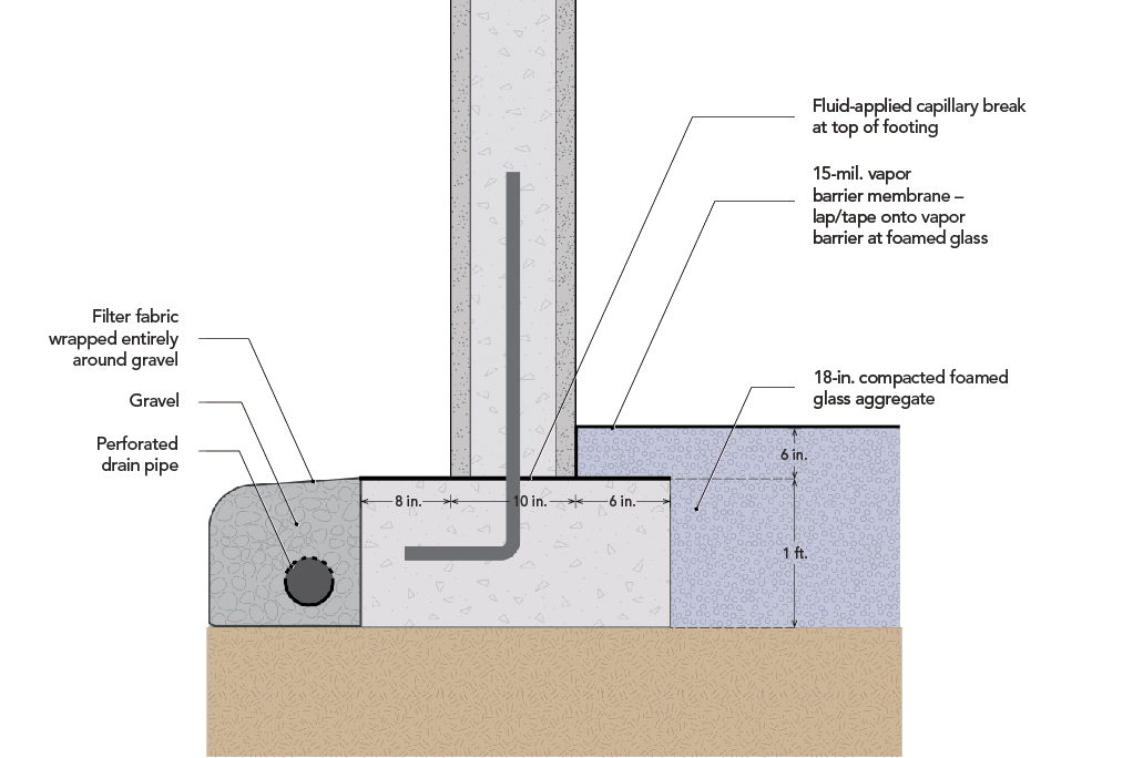
The ICCF Perfect Block foundation system they used does not include a conventional slab; foamed glass aggregate was used instead. According to Project Manager Ben Bogie, roughly 250 lb. per sq. ft. of lateral force is pushing inward at the base of the foundation, where the greatest earth pressure occurs (it decreases closer to grade). That pressure needed to be addressed to ensure the foundation’s structural integrity. The engineer’s original solution was to pour concrete beams across the entire foundation, connecting the footings so they would push against each other. However, that idea ignored a primary objective of the project, which is to reduce concrete. “It would have required nearly the same amount of concrete as a slab for this house—without the slab,” Ben explains.
The answer came in the form of StrataGrid geotextile fabric, which Ben describes as similar to chicken wire with its lattice web but made of 1/4-in.-diameter plastic; Tensar Geogrid products would work for this application too. It gets fastened to the top of the foundation footing with a termination bar and a fastener schedule from the engineer—in this case, every 8 in. The downward force of the backfill soil clamps the termination bar and fabric in place. “The more downward pressure there is, the more lateral pressure there is, but also the more clamping pressure there is on the fabric, locking it in place,” Ben says, adding that this technique is commonly used in stacked-block retaining walls. Here, it accomplishes what a 4-in. concrete slab would from inside the foundation—without the embodied carbon load.
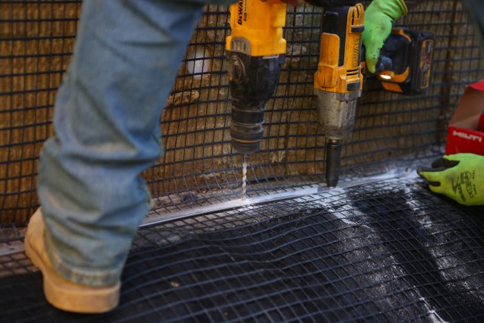
The product is 6-ft. wide and is cut to match the length of the footing section to which it is being fastened. It goes down folded to form two layers in an L shape; one leg comes out horizontally from the foundation wall and the other leg travels vertically up the wall. Then an 1/8-in. by 1-in. stainless steel termination bar is installed over the horizontal length; it is drilled and screwed onto the footing. The vertical leg is brought down to lay over the the horizontal lap, and the bar is sandwiched between the two layers to prevent the fabric from pulling out.
This is one of those cases when a common commercial detail makes its way into a residential application. Ben says this solution saved about $25,000 when compared to pouring a slab or the recommended concrete beams—plus it omitted roughly 60 tons of CO2 emissions.
_______________________________________________________________________
Kiley Jacques is senior editor at Green Building Advisor. Illustration by Patrick Welsh. Photo by Brian McAward.
Weekly Newsletter
Get building science and energy efficiency advice, plus special offers, in your inbox.


15 Comments
This seems like an innovative product that could have a lot of uses.
I understand how geo-textiles would retain soil, but how that translates into stopping horizontal forces against the footing or foundation, or how it is deployed eludes me.
Malcom,
It's basically acting as a tension mat. The plastic mat has tensile strength so as long at it's attached to the foundation footing and wall, it holds it back in place. With all of the downward pressure on the horizontal portion of the mat, it creates enough friction that doesn't allow it to slide towards the inside of the building. Like I said, the way it's described in words is good but the diagram doesn't explain it very well and is kind of misleading. Unless I'm just not reading it right.
Nelson,
I've only used the geo-textile mats to to retain the substrate under roads on slopes, so this is all new to me. The problem is probably mine but what I don't get is:
- Is it the screwed connection that actually holds back the footings?
- Where is that second piece located? Is it folded over the first one to form a sandwich? If so is there soil in between?
- If it runs up the wall I don't see the point at all. When I have had walls engineered to retain soils, they had large eccentrically placed footings. These relied on a good moment connection between them and the wall above. Something an L shaped mat wouldn't have.
What would be useful is a section that showed the geo-textile placement and some arrows representing the horizontal forces at play.
This reminded me of the L-shaped walls you mention, but those are to prevent overturning from forces up higher typically if the moment connection is considered important, correct? This would only prevent lateral movement down low. The screws do seem chintzy at first thought, but with enough I suppose.
and on second thought, 250 lbs. per sq. ft. isn't all that much really.
Tyler,
I would have been tempted to place it on the footings and pour the walls on top. But that's just back-seat driving. It works, and I think we now understand how.
Yeah that's an interesting thought. Some retaining wall builders will lay geogrid into the courses of their walls. similar concept.
Malcolm, bear with me I’m not an engineer but… the screw connection is the point at which the forces are transferred from the termination bar, sandwiched between the two layers (there is only an upturned leg of material during the process of attaching the bar and fasteners) and in to the concrete footing. I can’t speak to the quantifiable forces at play here well, but I can say that the fastener selection, spacing, and minimum distance from edge, was calculated and specified by the engineering team.
This was very much an Ah Ha solution late one evening by the engineer and is inspired by the construction of stacked block retaining walls where a similar method is frequently deployed.
Ben,
Thanks for the explanation. My initial mistake was thinking the termination bar and screws were just there to hold it in place until backfill - a bit like the fasteners on exterior foundation insulation. Once I saw them as a structural connection, it all makes sense.
I'm a bit late to the party (and I'm not sure I fully understand it either), but this seems like your road example except they have an elevated "road" going around the perimeter of the hole (ie. the house). The grid seems like it would stabilize the soils around the excavation; the attaching to the footings "locks" everything together.
Practical Engineering - How Soil Can Hold Up a Car
https://www.youtube.com/watch?v=0olpSN6_TCc
He goes into details and examples. For roads, the concrete wall is (largely) there for decoration and protection of the soil from the elements. This seems similar, but they are just using a house for those purposes.
Take with a pound of salt as I am arm chair engineering the thought process solely based on this article (ie. no calcs were provided).
Brendan,
Thanks. That makes sense. I think I underestimate the holding power of the screws and termination bar.
I would refer to this as geogrid, not so much geotextile, simply because of colloquial usage of what each respective product is used for and how they function.
You’re probably correct on that. It’s not a frequent material type for us to work with so there may be some confusion in my part.
Did my comment get deleted? I posted a reply with a little diagram (that Malcolm is responding to in his May 11, 2022 07:44pm comment), but now I don't see it.
I just wanted to know if my comment was deleted intentionally, or if it's a bug in the comment system.
Very clever! Simple, effective, with multiple benefits including reduced cost. Keep up the good work.
Log in or create an account to post a comment.
Sign up Log in