
Image Credit: David Goodyear
Image Credit: David Goodyear With some practice, we found a way to make sure the batt filled the stud cavity evenly, all the way to the inside corners. The first step in installing the ERV vent termination was to cut through the exterior foam sheathing and foam the vent into place. The dual vent for the ERV was installed as a single unit through the fiberglass batt insulation and the OSB air barrier. Drilling a neat hole through fiberglass batt insulation wasn't as hard as it might sound. Compressing the batt with a template of OSB allowed the drill to slice neatly through the fiberglass. An airtight hatch into the attic starts with an OSB box. It will be capped with 12 inches of EPS insulation. A catwalk between roof trusses will make life easier for the insulation installer.
More Guest Blogs


Editor’s Note: This is one of a series of blogs by David Goodyear describing the construction of his new home in Flatrock, Newfoundland, the first in the province built to the Passive House standard. The first installment of the GBA blog series was titled An Introduction to the Flatrock Passive House. For a list of Goodyear’s earlier blogs on this site, see the “Related Articles” sidebar below; you’ll find his complete blog here.
My plans called for fiberglass batt insulation in the stud cavities with an OSB air barrier to the inside of the wall and EPS foam sheathing on the outside of the house. The problem is that the walls are framed with 2x8s, and my check of local suppliers found there are very few fiberglass options for a 2×8 wall (7 1/4 inches deep).
Several companies make batt insulation in thicknesses of 8 1/2 inches (R-28) and 7 1/2 inches (R-22). Another option was to gang up batts of different thicknesses and R-values but this seemed complicated and installation could take twice as long. In either case, the insulation will have to be compressed into the wall cavity with the OSB. Yet another option was blown in fiberglass. At about R-29.8 it is the best option for conformity inside the wall cavity and provides the highest R-value. This would be my best option if budget allowed for it.
Before making a final choice about which products to use, I decided to further investigate the documented effects of compressing fiberglass insulation. I have heard people say you shouldn’t compress fiberglass insulation. However, this depends heavily on installation details.
So, can you compress a deep fiberglass batt into a shallow stud wall cavity? You sure can, and even though compressing the batt lowers its nominal R-value, you still end up with a higher R-value than a standard batt would provide. The formulas are pretty simple.
Final R-Value = Original R-Value + Change in R-Value
where,
Change in R-Value = 1/2 x (Percentage change in thickness) x (Original R-Value)
where the “Percentage change in thickness” is
100% x ( Compressed Thickness – Original Thickness) / (Original Thickness)
So for R-31 (9 1/2 inch thick) batt compressed into a 7 1/4 inch stud space, the percentage change in thickness is
100% x (7.5″-9.5″) / 9.5″ = -21%.
This translates into a change in R-Value equal to
1/2 x (-21%) x 31 = -3.3.
So the final R-value would be 27.7 in the cavity. This seemed like a good option. But there were some details to keep in mind and a few things to work around.
First, R-31 batts only come in a 24-inch wide width while the stud cavities are actually 22 1/2 inches wide because of the 24-inch on-center spacing of the studs. So every R-31 batt would have to be cut to the proper width. RESNET recommends insulation 1 inch bigger than the cavity (from what I recall). This is interesting because most manufacturers provide insulation at widths that are only 1/2 inch wider than the stud cavity.
I omitted blocking from the walls in order to provide a full stud space for insulation. This led to a minor problem: As the studs started to dry, they also started to warp. The cavities were 22 1/2 inches at the plates but up to 23 inches wide elsewhere in the cavity. Cutting insulation at non-uniform widths would be extremely time consuming.
My work-around was to use the whole batt in the cavity without cutting it to width. At 1 1/2 inches larger than the cavity in places, the batt would only be wider than the RESNET specification by 1/2 inch. The effect of this is compression along the width of the cavity. Since the R-Value changes linearly with compression, I would expect the same formula above applies to the width of the cavity also. So, using the above formula and my calculated R-value under compression (i.e. R-27.7) the insulation would have a variability from R-27.1 to R-26.8, assuming a perfect installation.
Fears of bulging walls were unfounded
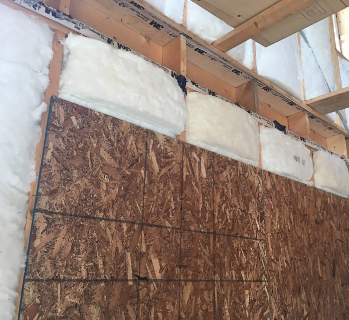
Several people suggested that this much compression would lead to issues with installation of the interior OSB air barrier — bulges in the OSB between the studs. We mocked up a batt installation and covered it with a sheet of OSB. We did need two people to install the mock up: one person to hold and compress the insulation with the sheet of OSB, and the other person to nail the OSB in place.
The trick was to start nailing at the bottom plate (a pneumatic nailer worked best). We then pushed the sheet in (compressing the insulation behind it) about 16 inches up the wall and nailed it again. We kept doing this until the full sheet was nailed. After installation was complete we ran a straightedge horizontally across the OSB and found no bulging from the insulation. The bending stress on the OSB across a 2-foot span appears nonexistent. Compressing fiberglass with OSB works fine. However I can guarantee that anything more than R-31 is very hard to compress. Don’t bother trying it!
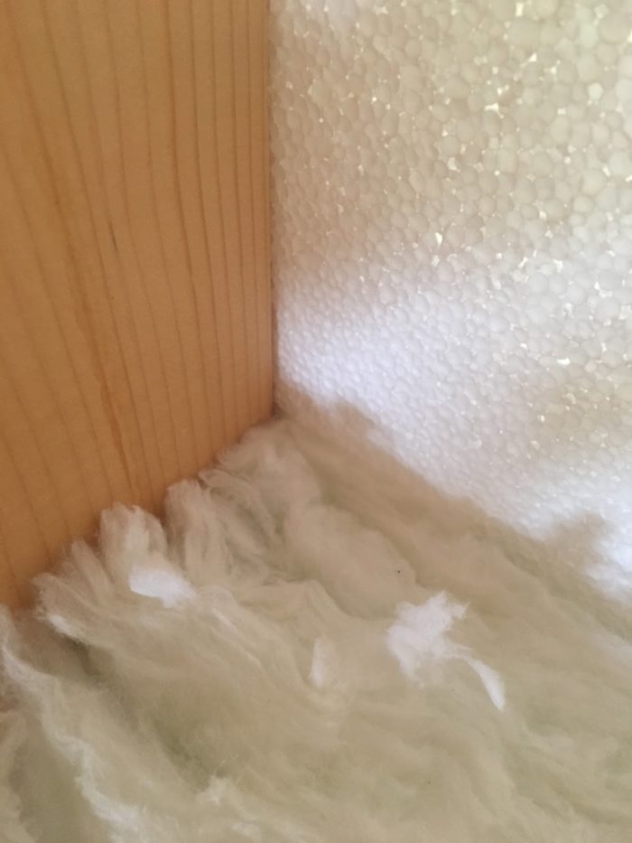
Installation of the batts was tricky at first. Simply pushing them into the cavity led to uneven filling. Repeatedly, the batts did not fill the corners of the wall cavity at the exterior side. To correct this we had to start by angling the batt into the corner while compressing it in width to fit into the opposite side. We would use our hands to pull the insulation away slightly and visually inspect the corners and tucked the insulation into the corners as needed. (See Image #2 below.)
The trick to making it puffy is to make sure the batt is tight-fitting but only about 1/2 inch bigger than the stud cavity in both height and width. The batt then slips in the cavity with ease and the center still bulges outside the stud cavity which will make for more uniform compression once the OSB is installed.
Having several people to install insulation makes the job move along quickly. However, it also introduces some variations in results. We inspected each other’s installations and watched one another’s installation method to narrow down the best way to achieve a good installation and came up with a set of rules. Our reasoning was that approach would yield a more consistent result.
Next, the air barrier
After completing the insulation, we started installing the first component of our airtight barrier, the OSB. We just followed the procedure we had mapped out with our mock-up. Since we wanted to keep joints to a minimum, we worked with full sheets.
Around windows, we typically placed the sheet vertically in front of the buck then scribed a line around the buck opening onto the OSB and cut the opening out with a circular saw. If the sheet covered the window, we ripped the sheet to the width of the nearest stud centered under the window opening so we could reach inside the buck opening to scribe the window opening. With this methodology we will be sealing two fewer joints per window when compared to installing individual pieces above and below the window bucks. In some cases this may not work, but I figured that more solid OSB would result in fewer air leaks. It also saved on expensive tape as well as time for caulking and taping.
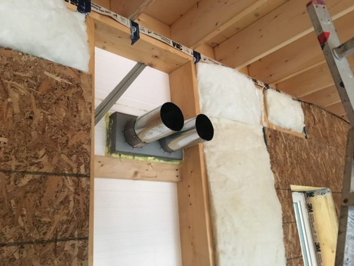
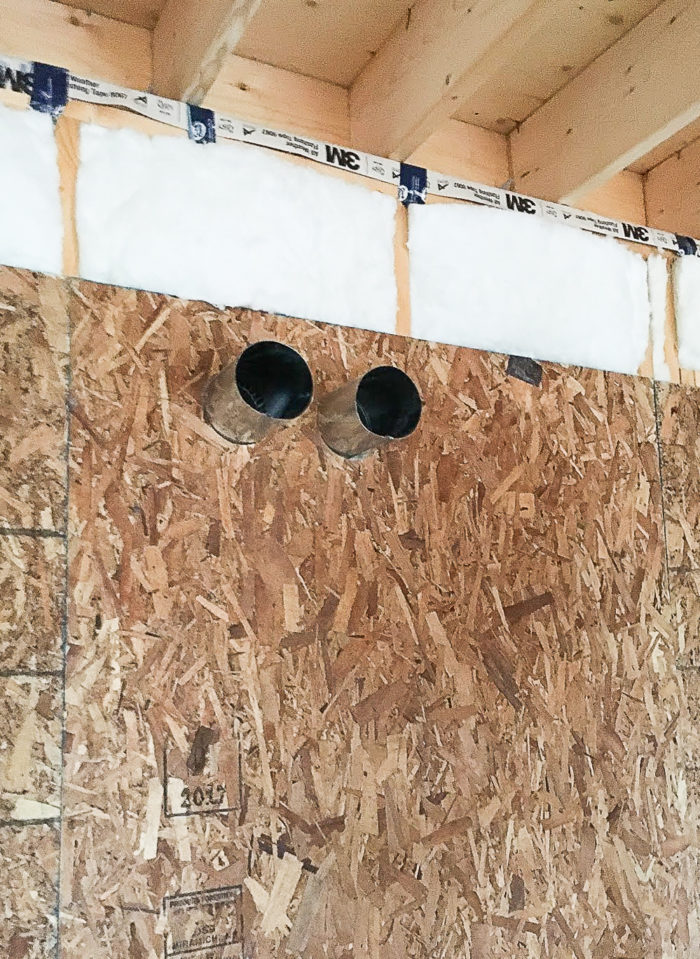
Some penetrations through the air barrier were easier to implement up front rather than waiting till later. The ERV vent termination was one of those penetrations. The termination fitting was the DVS-100 from Reversomatic. It is a dual vent that can be fitted into the wall in a single piece. The termination fitting was fitted into the wall cavity from the exterior. Extension pipes were added to the termination and spray foam was installed around the unit. The spray foam was trimmed so fiberglass would fit nicely around the pipes.
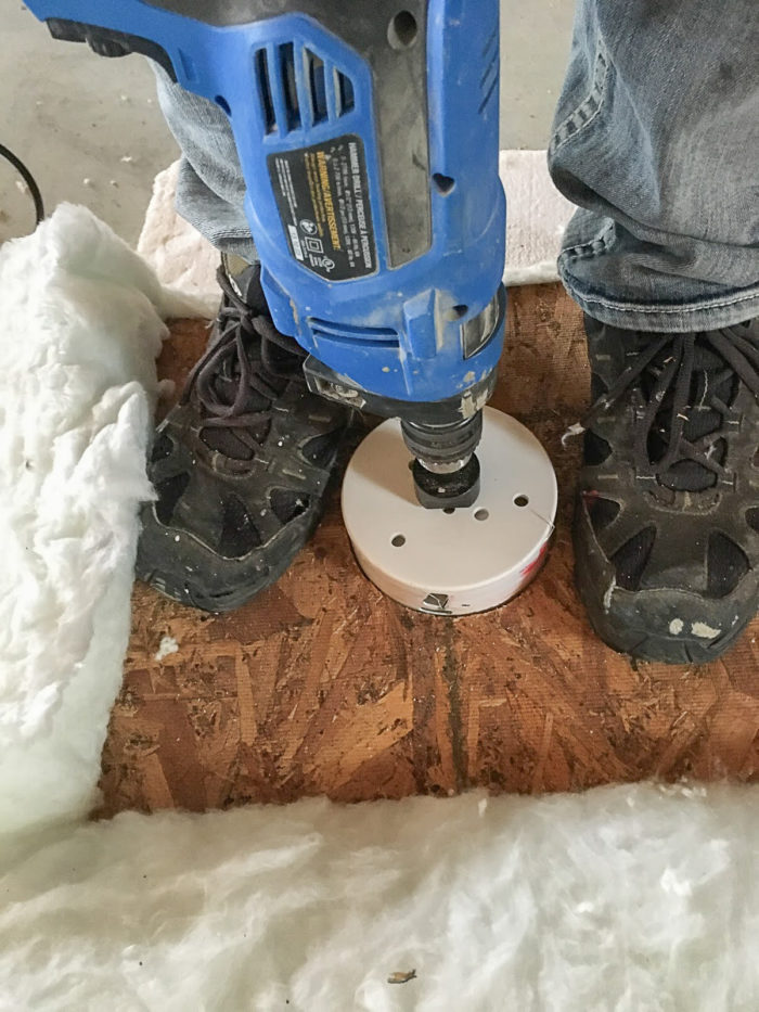
We marked out where the penetrations would be on a sheet of OSB and drilled the holes necessary for the vent pipe penetrations. (See Images #3 and #4, below.) In order to get nice tight insulation around the vent pipes, I had to figure out how to drill holes through fiberglass. Using a template placed on the batt at the right location, I stepped onto the templates with all of my weight. A drill with a hole saw could then be used to drill the hole locations to give nice round holes for fitting around the vents. (See image #5 below.)
Insulation for the attic
Attics are one of the neglected spaces in the our homes — an afterthought, really. Many trusses are designed the same way they were years ago. There is no thought put into the lack of insulation above the top plate on exterior walls. Heeled trusses [also called raised-heel trusses or energy-heel trusses] were developed as a solution to this problem. Adding a small heel enables deeper insulation over the top plate of exterior walls and helps prevent thermal short-circuiting to and from the attic space.
It seems that raised-heel trusses may become a mainstay for the future since code changes now require attics to be insulated to a minimum of R-50. Large heels mean more blocking and higher baffles to combat the effects of wind-washing on the thermal effectiveness of the attic insulation. The key here is to direct any wind (entering the attic through the soffit) far above the layer of insulation. The air contained in the insulation remains stagnant which maintains its thermal effectiveness.
Adding insulation to an attic is pretty cost-effective — even for a Passive House. There are several blown-in insulation choices available in our local market. Namely, cellulose and fiberglass. At about R-3.26 per inch, cellulose seemed to give the best value for my dollars. The manufacturer (Thermocell) was able to provide an R-value based on the depth of insulation required. The fiberglass provider wasn’t able to specify above R-60 so it was going to be a matter of blowing in extra and crossing our fingers. Even if they extrapolated the depth required, the initial thickness was going to be higher than cellulose in order to account for settling.
The cost of fiberglass is slightly higher than cellulose and would require higher baffles which would further increase the total cost of the installation. There are many more reasons for choosing cellulose (which I will explore in a future post), but the main point here is that I need lots!
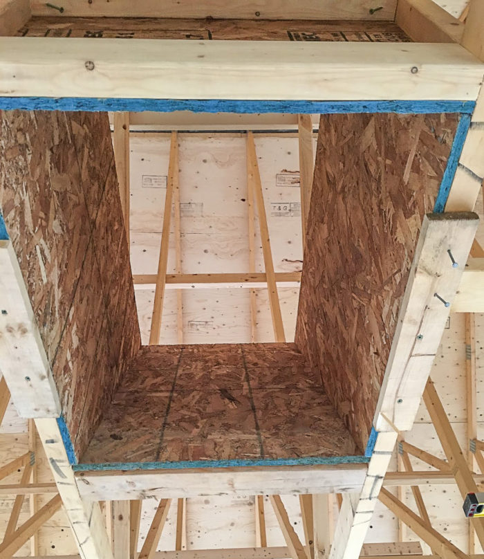
Building an attic hatch
Air sealing an attic hatch is not an easy task. Fortunately, my designer provided great details for the attic opening. It’s basically an OSB box with a sloped end. (See Image #6 below.) The OSB box was framed between the attic trusses in the middle of the future hallway. (Framing the interior is yet to start.) The box is about 32 inches high. At this height, it is about 6 inches above the top of the insulation.
The attic hatch door will be insulated with EPS. Luckily enough, I have lots of 4-inch scraps left over from my foundation. I will probably make it 12 inches thick since I can then just stack three layers of 4 inches each. This being said, I had to plan ahead for how the person entering the attic will deal with placement of the attic door. What I came up with is a landing at the top of the attic hatch opening where the attic door can be placed after it’s popped off the hatchway.
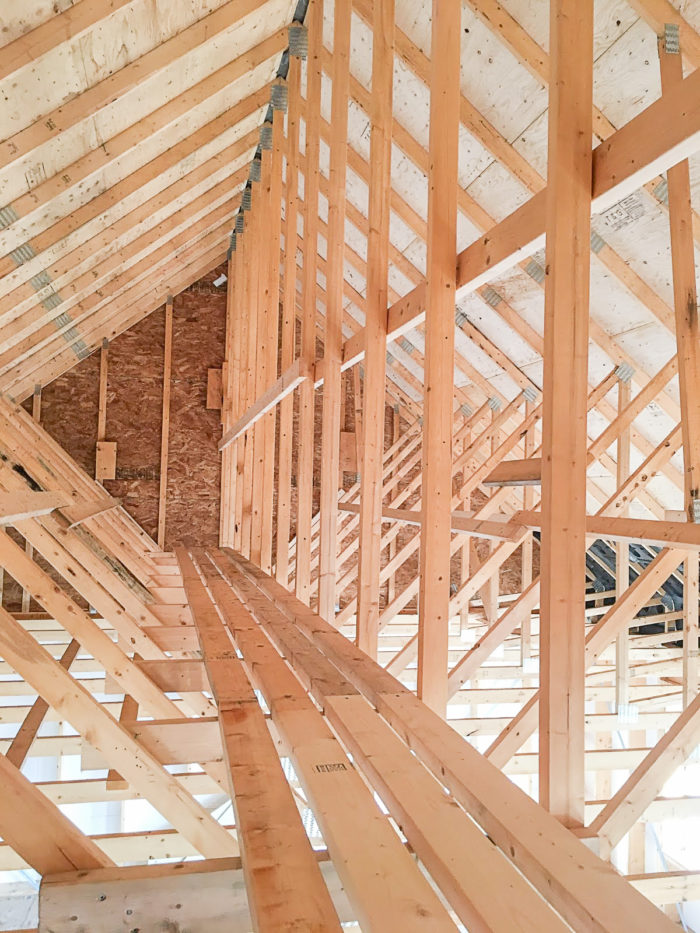
With 26-inch-deep insulation, it’s not going to be an easy task for the insulator to walk around in the attic, so I had to think ahead about how to make his life easier when blowing the insulation. A catwalk supported by the trusses was easy to make with some 2x4s. (See image #7 below.)
The catwalk runs about 32 feet along the length of the attic at a height of 32 inches above the attic deck below. It will be much safer than trying to navigate the attic while treading on truss webbing and pulling a large hose around. With the catwalk situated approximately in the center of the attic space, the insulator should be able to reach either side of the house. It will also make future inspections much easier than wading around in 26 inches of insulation!
Weekly Newsletter
Get building science and energy efficiency advice, plus special offers, in your inbox.


8 Comments
Attic Hatch
I like how you included the attic hatch/ cat walk in your design.
Attic hatches seam to be omitted altogether in high performance homes for obvious reasons (big hole in your air barrier!). But, like you pointed out, what if there is a leak that needs to be inspected? What if a rodent is up there? Cutting a random hole in the ceiling and getting covered in cellulose doesn't sound like fun.
Sure, a gable vent on hinges would solve the problem perhaps. But I prefer the look of ridge vents personally....
I would be curious to read what the rest of the GBA community thinks of attic hatches in high-performance homes. Thoughts anyone?
Response to Rick Evans
Rick,
There are three approaches:
1. Install a hinged door on the gable, accessed by an outdoor extension ladder.
2. If there is an attached garage, create an attic hatch in the garage ceiling.
3. Build a very well insulated hatch with weatherstripping and multiple latches, and install the hatch in the ceiling of an upstairs hallway.
Rick
There are also proprietary solutions:
https://www.foursevenfive.ca/wippro-klimatec-160-the-only-passive-house-certified-attic-stair/
Even though attic hatches pose a problem in high performance houses, they can't be omitted as they are required by code.
Rick, Malcolm
with good details, a good air tight attic hatch can be pretty simple to construct and install onsite. the proprietary ones are pretty expensive. So far, the hatchway has cost nothing but scraps of OSB and about 1 tube of acoustical sealant and some 3M Tape. The door will be painted 3/4 plywood and I have lots of left over foam to add to the top side. Id say the cost is less than a couple hundred dollars if you add everything up. I did toy around with the idea of a gable end entry but have heard people say that they had nothing but problems with water leaking in. In our climate I could see that it would lead to water problems so opted for an interior hatch. As for the catwalk I think its a necessity. without it I'm not sure how anybody could get around safely. I've been up there and having the catwalk makes a visit to the attic much more enjoyable!
David
I agree. A good catwalk often makes the difference between a homeowner going up periodically to check the attic, and never venturing in at all.
Because our climate here in thePNW makes covered outdoor space something it's good to include in any design, I've frequently been able to incorporate attic access under porch overhangs where it is well protected.
The chief benefits of having it accessible to the outside are that most of the work you may do up there is messy and it's nice not to trek all that mess through the inside of the house. It also allows you to get long pieces of lumber or conduit into the attic without maneuvering it through the interior.
You can see an unfinished one here in the breezeway of a house I built:
Mfg Chart for compressed insulation
Here is a chart for compressed insulation 9.5" R-30 into a 7.25" bay is R-25 they don't list how they determined the values.
http://www2.owenscorning.com/literature/pdfs/10017857%20Building%20Insul%20Compressed%20R-Value%20Chart%20Tech%20Bulletin.pdf
Great Discussion!
Thanks for the insight regarding attic hatches. Lots of wisdom here for the GBA community, as always.
Tim - compressed insulation Rick - Hatches
I found this document: https://insulationinstitute.org/wpcontent/uploads/2016/08/Compressed_R_values.pdf
it describes the calculation procedure. The key point is that you can compress insulation. As an example, an R12 batt fills a 2x4 cavity. If you compress it you get higher R/inch but you have less inches of insulation in the 2x4 cavity because it's no longer filled. For example if you fish insulation behind a wire and leave it compressed in the wall behind the wire you end up with a void in the wall. that air void can decrease the performance of the wall. however if you compress a R20 (2x6) into a 2x4 cavity you get a filled cavity but the R value will be more like 15. you gain R 3 by using the R20 bat compressed compared to using the R12. There are trade offs here. you pay more for the R20 batt, but if you can get a good deal on insulation it makes sense to purchase the thicker batt and compress it.
WRT the hatch, I have to credit the design company, Passive Design Solutions, for the details. They have designed many homes and provided me with a great set of plans.
Log in or create an account to post a comment.
Sign up Log in