
More Green Building Blog


This month, I’m tackling heat flow—or at least aspects of it. I’m going to assume a project that has already addressed the superseding phenomena of water, air, and vapor. Here I’m looking strictly at thermal control.
So, we’ve got an imaginary structure in mind, and now we want to live in it—comfortably. Of course, comfort is subjective. For me, it means I don’t have icicles hanging from my mustache in the winter, and I’m not sticking to every surface I touch in the summer. To achieve that while avoiding unnecessary energy costs, we need to be smart about when we let heat in or out.
Heat moves via three mechanisms: radiation, convection, and conduction. Ideally, we want to limit all three as much as possible without spending more money to do it than the effort will save over our lifetime—or maybe the lifetime of our kids. In order to do that, we need to insulate. And to insulate properly, we need to know how to quantify a material’s ability to perform optimally.
Vive la résistance
R-value is the one number all builders know. But what is it really? Let’s go to the omnipresent ASTM International for some insight, and then we’ll pick it apart. C168-19 defines R-value as:
Resistance, thermal, n: The quantity determined by the temperature difference, at steady state, between two defined surfaces of a material or construction that induces a unit heat flow through a unit area.
R-value is about resistance. It’s a measurement of how much a material can slow down the movement of heat between two surfaces, such as the inside and outside of a wall.
This is tested by squishing a piece of insulating material between two metal plates,…
Weekly Newsletter
Get building science and energy efficiency advice, plus special offers, in your inbox.

This article is only available to GBA Prime Members
Sign up for a free trial and get instant access to this article as well as GBA’s complete library of premium articles and construction details.
Start Free TrialAlready a member? Log in


14 Comments
There is the phenomenon of Infiltration Heat Recovery so you can add this to the equation. It is behind a paywall but I may have the LBL study downloaded somewhere or maybe another GBA member has it.
https://eta.lbl.gov/publications/infiltration-heat-recovery-building
The attachment also gets into Infiltration Heat Recovery, a complicated formula.
I just dug up a copy (https://www.aivc.org/sites/default/files/members_area/medias/pdf/Inive/LBL/LBNL-51324.pdf) and just getting through the opening paragraph made me smack myself on the forehead... duh. Of course there’s heat lost or regained by interstitial airflow. Can’t wait to dig into that over the weekend. Thanks!
I appreciate your describing these in intuitive and practical terms from a builder's perspective. From an engineer's perspective, the explanations here aren't quite technically correct, so I'm going to explain how I would correct them.
First, what all of these have in common is that they relate a temperature difference, either between indoors and outdoors or between two surfaces, to a steady heat flow. That heat flow is typically in BTU/hour, but the hour there doesn't mean it's describing anything dynamic or changing with time. The wording used is sometimes the quantity of heat (BTU) per unit time (1 hour), and sometimes heat flow (where BTU/h is assumed), and those might sound different, but they are just two ways of saying the same thing. So the relationship between all of these is simpler than it might seem.
Next, let's talk about R-value and C-value. R-value is something most builders know. It's the thermal resistance of one square foot of insulation, and the heat flow through it is Q = A ⋅ ΔT/(R-value), where ΔT is the temperature difference between the two surfaces of the insulation and A is the surface area.
C-value is less commonly used in engineering or building, but it's simple the reciprocal of R-value: C-value = 1/(R-value). This allows us to write Q = A ⋅ ΔT ⋅ (C-value). That sounds easier, because multiplication is easier than division, but the advantage of R-value is that if you layer insulation--maybe two layers of R-8 foam--the resulting overall R-value is just the sum: R-8 + R-8 = R16. The corresponding C-value calculation is more complicated, so that's one of the reasons R-value is more popular.
People who are familiar with U-factor are probably thinking "wait I thought that was what U-factor was--why is he calling it C-value?" U-factor and C-value are almost the same. The difference is that C-value is describing a component or material, and U-factor is an "all-in" number. That can mean it's a "whole wall" calculation, including the studs, the wallboard, the sheathing, the siding, etc. Or more commonly, it's a "whole window calculation", including the frame as well as the glass, the air spaces between the glass, etc. And that "etc." includes the "air film" on the surfaces. The practical consequence of that is that the formula Q = A ⋅ ΔT ⋅ (C-value) looks almost the same for U-factor. The only difference is that in Q = A ⋅ ΔTa ⋅ (U-factor), the temperature difference is the difference between the air temperatures inside and out, not the surface temperatures on the two sides of the insulation or other material. With an R-40 wall, those surface temperatures are very close to the temperatures or the air inside and out so it doesn't matter which temperatures you use, but with a low performance window, the interior surface temperature is much colder than the interior air temperature. Hence the need to make that distinction and use U-factor for windows.
I didn't talk about K-value, but I think this is enough for one comment ...
Thanks for the response Charlie! I appreciate you cutting me a bit of slack. I walk a fine line of my own limited knowledge of physics and trying to use it to simplify building concepts while also treading deep enough to expand into the distinctions between U and C. For most builders, architects, owners, treating U and R as reciprocal is fine but I was hoping to at least crack the door on the concept that there are other contributing factors to the performance of a system others than the rough sum of its parts, IE-air films.
my simplistic take: K is to C what permeability is to permeance. (K is conductivity and, generally, not dependent on thickness. C is Conductance and accounts for thickness).
Its helpful to consider that the -ity and -ility endings are the sort of 'intrinsic' properties, (think 'ability') whereas the -ance -ence endings account for thickness, and are absolute (think 'existence').
If you had the -ance -ence numbers, you wouldn't need to know the thickness to proceed with assessing the assembly. Like R-value).
Tyler, I like your word-ending tip.
Another "-tivity" word is "resistivity". Thermal resistivity isn't a word used much in the building field, but it's the same concept as R-value per inch, we we talk about a lot. K, or conductivity, is the reciprocal of resistivity--in other words, K = 1/(R-value per inch).
Ben, I like the fact the GBA provides a forum for conversations between people who come at this from different backgrounds and different vocabularies. It goes both wasys--most of us who understand the physics/engineering theory have a lot to learn about the practical aspects.
Very helpful explanation.
"With an R-40 wall, those surface temperatures are very close to the temperatures or the air inside and out so it doesn't matter which temperatures you use, but with a low performance window, the interior surface temperature is much colder than the interior air temperature. "
Charlie (or others),
This is interesting.
We always assume that the temperate drop across an assembly drops linearly in proportion to R-value, but with the assumption that the inside wall surface is the same temp as indoor ambient, and the outside wall surface is the same temp as outdoor ambient (well, we acknowledge it's not when it comes to radiative cooling I suppose).
As stated, this seems more an estimation that 'practically' works for higher R-value assemblies. It's not true with a window, and I imagine it's not true with low R-value assemblies, like a sheet of plywood. Is there some threshold here? Is it linear, exponential...?
I assume it has to do with rates of energy pass-through; energy lost vs energy gained at the surface boundary. For a given inner wall temp, I picture an equilibrium were energy lost equals energy gained. If energy lost is high enough, energy gained can also be quite high (the energy gained via interior ambient), yet still not raise the temperature to that of ambient if the supplied energy is limited.
Are air films playing a role here, or is it all about the energy budget?
If you want a really rough estimate, you can assume the interior air film is R-1, and still ignore the exterior air film. If you have a poorly insulated wall that's, for example, R-4, then the total is R-5, and 1/5 of the temperature difference is across the air film. For example, if it's 20 F outside and 70 F inside, the 50 F difference is 40 F across the R-5 wall, and 10 F across the air film. That's the equilibrium where the surface is losing and gaining heat at the same rate, with the simple R-1 approximation for the air film.
But that's a rough approximation: the heat flow by convection is not linear with temperature difference, so that R-1 changes according to how big that temperature difference is. That's interesting, but not particularly important: If you've got an R-5 wall, you should worry about how to make it at least an R-13 wall, rather than worrying about whether the air film is R-1 or R-0.783.
The term "air film" is a bit of a misnomer--it's a combination of the convention heat flow, for which most of the temperature difference is across a thin surface layer, and radiation heat transfer. For typical room temperatures, especially with a well insulated wall, the radiation heat transfer from the objects in the room to the paint on the wall actually dominates. But this is of now practical consequence. If you put aluminum foil on your walls to halt that radiation heat transfer, the convection would take over and you'd only gain about an additional R-1 at best.
It’s ALL about air films, more appropriately termed “boundary layers”.
Let’s consider windows or other fenestration units. Because these are exposed to both the exterior and interior of the house, it makes sense to consider the effects of these in-use conditions on the thermal performance of the window. We know from measurements that the interior surface of the IGU is less than room temperature (considering it’s colder outside). This temperature gradient causes a pressure gradient that generates natural convective air currents. Because air has some viscosity, the speed of the air directly at the window surface is zero, and and increases to the bulk indoor air speed within a short distance termed the boundary layer thickness. Suppose we try to ignore this thin layer. Then, we would have to assume a sudden temperature change between the interior surface and the air immediately surrounding it. This requires infinite energy transfer, which cannot happen. The goal then is to quantify the heat transfer coefficient, U, of this boundary layer. It’s complicated but fortunately engineers have thought a lot about it. From experimentally-verified conditions, the lower limit of natural convection-driven heat transfer is about 1.35 BTU/(h . ft^2 . oF) ---BTU per hour per sq. foot per degree Fahrenheit--sorry for the crappy font. The inverse of this is the R value of this layer…~0.74 in Imperial units.
Now consider outside conditions. Here, both natural and forced convection are encountered, and forced convection of wind will dominate. The heat transfer coefficient of this outside boundary layer depends on the wind speed; the higher the speed, the larger the U. By convention, windows units are measured at a simulated wind speed of about 13 mph. Under the standard conditions, a U value of about 5.1 (same units as above) results.
How does this affect the overall performance of the window? The presence of a boundary layer will always improve the apparent performance. Consider an IGU with a U value of 0.25 that is determined by measuring the heat flux while assuming a temperature gradient as the difference between outside bulk air and inside bulk air. (The inverse of this value is equivalent to the R value of the window; in this case R=4). To calculate the overall standardized performance, Ust:
1/Ust = 1/Uigu +1/Uinside + 1/Uoutisde
1/Ust = 1/0.25 + 1/1.35 + 1/5.1
Ust = 0.20
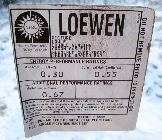
You now have an apparent resistance of 5 instead of 4. So when you buy a window rated U = 0.2, 25% of that performance comes from the fact that the National Fenestration Rating Council (NFRC) ratings account for these boundary layers under well-defined conditions. I should note that the ratings account for area-averaged U values of center-of-glass, edge-of-glass, frame, etc; therefore the rating is not simply based on an analysis of the IGU.
I see that Charlie Sullivan has commented below, and gives a rough estimate of R=1 for the inside boundary layer. This agrees with my value of 0.74. I will also note that the effects of radiation heat transfer are independent of these boundary layer considerations, which are strictly convective. I’m pretty sure radiation is not considered in the reported fenestration U value.
Fred, your comment is helpful and accurate with one exception: the radiation comment at the end. Your R-value for the boundary layer of 0.74 includes the radiation heat transfer. If you look in the ASHRAE fundamental "fenestration" chapter they give that value for a ΔT of 5 F ΔT, for emissivity 0.9. They also have a number for 0.1 emissivity, blocking most of the radiation heat transfer. In that case, the value goes up to R-2. That's essentially the value for convection alone, without significant radiation. In other words, U for convection is about 0.5, and the remaining 0.85 needed to get up to a total of 1.35 is from radiation.
And U-factor for windows does include radiation heat tranfer. In winter, that's from the room to surface 4, between surface 2 and 3, and from surface 1 to the outdoors. That's why low-e coatings lower the U-factor. Note that no longwave thermal radiation goes through the window glass, which is opaque in that wavelength range. It only plays a role in heat transfer to, from, and between panes of glass.
Thank you Charlie. I stand corrected, and I should have investigated the issue more thoroughly. I'll definitely look into it. I surely agree that radiation plays an important role in the performance of the unit...as determined by the performance of the low-e coatings. I think my understanding is that this mechanism is implicitly accounted for in the U rating through the actual performance measurements of the particular IGU, but is not explicitly modeled as part of the heat flux equations used to report U-factors? I don't know.
It's definitely modeled as part of the simulations used by NFRC to calculate U-factors.
The THERM 7 / WINDOW 7 NFRC Simulation Manual says: "The radiative energy flux leaving each surface is calculated from the Stephan-Boltzmann law using the surface infrared hemispherical emissivity and temperature. The net radiative flux between radiating nodes divided by the associated temperature difference gives an effective radiation heat transfer coefficient."
And it's also inevitably part of the measurements.
Maybe the confusion is that when you then calculate the heat flow through the window, you use Q = A ⋅ ΔTa ⋅ (U-factor), which looks like an equation for heat flow by conduction, but it is really an approximate equation for the net result of a complex process that includes conduction, convection and radiation.
Great info; thanks! Obviously I'm not an expert in this, instead a curious consumer with an engineering background who is trying to understand window U ratings.
Log in or become a member to post a comment.
Sign up Log in