
Image Credit: M. Chandler
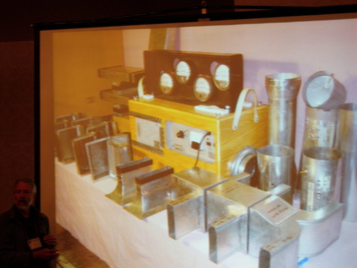
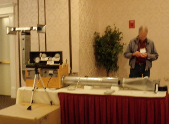
Image Credit: M. Chandler David used velcro duct tape to quickly assemble different duct fitting combinations to show the impact of fitting selection on static pressure and air flow.
Image Credit: M. Chandler The throat is where the eddy forms, and the eddy reduces the available free area of the duct. But turning vanes can make a big difference.
Image Credit: M. Chandler How the ducts connect to the air handler is the first and most actionable consideration, if the designer gives you enough room for those critical first few fittings.
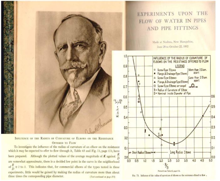
Image Credit: M. Chandler It's great to be able to bring in an illustration from my great-grandfather's book written in 1892. The graph shows that there is a sweet spot in pipe flow when the radius of the elbow is two to three times the pipe diameter.
Image Credit: M. Chandler
More Green Building Blog


In the Southeast where I live and build, we mostly rely on ducted HVAC systems for heating and (especially) for cooling. So when I attended the Westford Building Science Symposium in early August, I was very excited to sit in on David Hill’s presentation on HVAC systems, especially as Dr. Joe’s introduction paraphrased Samuel Clemens’ observation: “It ain’t so much the things we don’t know that get us into trouble; it’s the things we know that just ain’t so.”
I’m especially interested in situations where new research is disproving assumptions behind accepted best practices, since these re-evaluations lead the industry to fine-tuning and improvements. David Hill’s presentation on duct design was full of these. The “take-aways” I got from this are:
- to examine the way we do duct take-offs and fittings,
- to place an “evase” between the fan outlet and the trunk or the split for the zone valves leading to the trunk in a zoned systems,
- to look very carefully at filter placement and the taughtness of flex duct, and
- to start doing all this in the design phase so we allow enough room to implement thoughtful duct design before the sheetrocker removes the opportunity for improvement.
Pressure drop parasites rob equipment of efficiency and durability
Duct systems contribute to bad HVAC performance by increasing static pressure and reducing air flow through the air handler. Air is only capable of carrying 1,000 BTUh per 31 CFM at the 30 degree temperature rise typical of heat pumps. (A gas furnace will typically run with a 30-60 degree temperature rise.) A 2½-ton (30,000 BTUh) heat pump with a 30 degree rise will need to move 31 cfm/Kbtu x 30 KBTU = 960 CFM.
Static pressure and flow are directly related to the electrical power required at the fan, which uses 80% of its energy to overcome static pressure and only 20% to create air velocity. This is why the SEER ratings of ductless minisplit equipment are much better than of the exact same model with ducted /cassette options. Ducts matter.
The numbers here are infinitesimal – 0.011 PSI
Static dressure drop is commonly stated in terms of “inches of water column” (abbreviated “inAq” or “inH20”) or pounds per square inch (PSI). 1 PSI = 27.68 inH2O = 2.3 feet of head = 0.68 atmosphere = 6895 pascal (newtons per square meter).
Pressure drop created by fittings in a length of duct is expressed as “equivalent duct length” — that is, the length of straight duct of the same cross sectional area that would create the same static pressure drop as the fitting in question.
Air handlers are typically designed to operate against a static pressure of 0.3 inH20 or roughly 75 pascals or 0.011 PSI. The numbers here are infinitesimal compared to the 18 feet of head = 7.8 PSI numbers I’m used to dealing with in plumbing design.
It’s important to understand static pressure because a 2½-ton (30,000 BTUh) heat pump needs to move 960 cfm to transfer that heat at a 30 degree temperature rise, but if the static pressure is too high, air flow will be reduced, limiting its ability to remove heat from the coil and transfer it to the home.
As many as 80% of ECM motors use more power than the PSC motors they replaced
A typical 1/3 hp PSC motor is designed to move 1,000 cfm at .30 inH2O while drawing 335 watts. At a higher static pressure of 0.6 inH2O, the same motor will deliver only 400 cfm, but will only draw 240 watts doing so, as the blower wheel blades simply recirculate an increasingly large percentage of their air, doing less work and thus drawing less power. A similar unit with an ECM blower can deliver 1,000 cfm at 0.3 inH20, drawing 225 watts; the ECM motor will still deliver 1,000 cfm at a higher static pressure of 0.6 inH20, but will draw 350 watts to do so. In other words, at a higher static pressure, the ECM motor continues to deliver 1,000 cfm (unlike the PSC motor, which delivers less air as the filters clog up). Gavin Healy commented that he has seen 4-ton and 5-ton gas furnaces with ECM blowers that were drawing 900 to 1,200 watts.
David Hill believes that as many as 80% of energy-efficient ECM motors in HVAC systems actually consume more power than the PSC motors they replaced (but they do a better job of delivering the air across the coil and to the house).
If the blower is only delivering 400 cfm due to that 0.6 inH2O static pressure, the ability to move heat is cut 60%, and that excess heat builds up in the cabinet and gets returned by the refrigerant to the compressor. The compromised equipment runs at high temperature/refrigerant pressure, returning more heat to the outdoor compressor. It runs longer and harder, with greatly reduced efficiency, both because it’s trying to heat refrigerant that is already hot and because the heat isn’t getting to the home to satisfy the thermostat.
The “ductulator” only addresses 10% of duct losses
Too much attention in duct design gets focused on pressure losses due to duct friction. Part of the reason for this is that architects don’t give the HVAC crew enough room to take advantage of opportunities for better trunk line fittings and cabinet optimization, so duct length and sizing end up being the only variables they have control over.
While flex duct that is pulled tight and well supported has less loss than slack or poorly supported flex, the friction component calculated using a ductulator (duct calculator) is not the primary villain here, at only 10% of losses. “System effects” of the furnace or air-handler cabinet, as well as coil and filter losses adjacent to the blower inlet and discharge, are second in importance at 30%. Duct fittings represent 60% of losses, and are therefore far more significant in actual practice.
Evase opportunity and squirrel cage Aikido
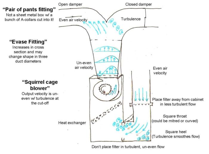
The first opportunity for improvement is to give the air handler room to breathe on both the return and supply side of the cabinet. An “evase,” a piece of duct that increases in size and may change from rectangular to round in cross-section as it moves away from the air handler, helps bring the air out of the air handler in the same way that loud “megaphone pipes” on a motorcycle help pull exhaust from the manifold.
When we look at how air escapes from a centrifugal (squirrel-cage) blower, we discover that it is moving at a different velocity depending on where in the exit cross-section it’s located. If we can give it three times the duct diameter to come to equilibrium before asking it to change direction, more of the energy in the fast air stream will be imparted to the slower air around the edges and close to the throat, and less will be lost to system effects.
When choosing a cabinet for best air flow characteristics, we will be better served by equipment that pulls the air through the coil and exits through the blower rather than entering the cabinet through the blower and exiting through the coil.
Don’t hit filters at an angle or with turbulent flow
Similarly, when we look at the static pressure impact of the filter, we discover that it is very much in our interest to hit the filter square on with the air stream rather than putting it in the wildly disturbed flow at the outlet of an elbow or angled to the stream as often happens when it’s on the intake of the air handler.
The difference of the pressure curves of clean versus dirty filters is pretty shocking as well. In one example, an ECM system with a clean filter running at 0.2 inH20 at 1,100 CFM drawing 225 watts ran with a dirty filter at 0.5 inH20 at 1,100 cfm drawing 320 watts. If it had been a PSC motor on that air handler, the flow would have been reduced on the order of 40-50%.
My takeaway here is that in homes with 100% of return air duct inside the conditioned envelope, it may be a good idea to install multiple air filters in the grilles where they have uniform face velocity across the full area of the filter and are readily accessible for service rather than in the mechanical room.
Mind your elbows and wyes, especially in the trunk line
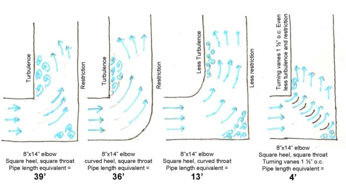
The biggest thing we can do is look more carefully at elbows and take-offs in the trunk. When air exits a trunk at a right-angle fitting, the shape of the heel of the fitting is much less important than the shape of the throat. According to the ASHRAE Duct Fitting Database, an 8×14 elbow with a square heel and a square throat at 500 fpm air velocity has a pipe length equivalent of 39 feet. If you radius the heel, the equivalent drops to 36 feet. But if we leave the heel square and radius the throat, the equivalent length drops to 13 feet!
What’s happening here? When the air passes that sharp throat, it creates an eddy — a pocket of turbulence just downstream from the throat (similar to the eddy you rest in while white water kayaking). Unfortunately, this eddy has the effect of reducing the usable pipe diameter and restricting flow. (In hot water distribution, this same eddy in the pipe mixes cold and hot together, increasing the amount of time it takes the hot water to push the cold out of the way and get to the fixture.) The square heel also gets clogged with turbulence, but in this case it converts it to a radiused heel with a bit more drag and doesn’t restrict cross-sectional area.
My great-grandfather told me so
The way that elbows reduce flow in HVAC systems is similar to how they increase delivery times in hot-water distribution systems.
This gives me an opportunity to share some images from my great-grandfather’s book, Experiments Upon the Flow of Water in Pipes and Pipe Fittings made in Nashua, NH 1892, in which he demonstrates experimentally that “for commercial elbows … little would be gained by making the radius of curvature more than about three times the corresponding pipe diameter.”
Got “turning vanes”?
That first elbow with a square throat and heel but with turning vanes installed at 1 1/2” OC has an equivalent duct length of 4 feet! The vanes break the air flow down into 1 1/2 inch slices, and each slice is directed individually in a way that effectively minimizes the size of that eddy.
Increasing the size of the vanes and spacing them further apart reduces the effective length even more, but increases the difficulty of production and the potential for error in placement and for restriction if a vane comes loose over time. Using an elbow with smooth heel and throat and three full length vanes can reduce the effective pipe length to one foot!
Start with a third-party HVAC designer and give the tin-knockers room to practice their craft
Getting your HVAC contractor to adopt these practices seems likely to create a different type of static pressure. I have a hard enough time just getting mine to implement curved fin ceiling registers with interior supplies. But I’ve had pretty good success with hiring a third-party engineer to do my Manual J, S, and D calculations and then including floor plans and sections of the mechanical room on the prints (a.k.a the “funny papers”).
HVAC installers quickly realize that their liability for the performance of the system is favorably impacted by bringing in a third-party engineer to take responsibility for the calculations and duct design. If you don’t calculate and draw out what you hope to achieve, there will be no place to begin discussion or collaboration.
Start with the mechanical room, the trunk, and the longest runs. Focus on minimizing fittings overall, and (at least) putting 45 degree gussets if not radius’s on the throats of your take-offs and elbows. Pull the filters away from the air handler to a place with clean, undisturbed parallel air flow where they can be easily inspected and serviced by the homeowners. Design-in room for an evase on the supply side of the air handler.
The opportunity to recognize and correct pressure drop parasites in bad duct design is before they are covered in drywall.
Weekly Newsletter
Get building science and energy efficiency advice, plus special offers, in your inbox.


7 Comments
Great information from David Hill
Refreshing topic, Michael. Practical, affordable and worth implementing, to the benefit of the entire building community and the common good. Refreshing compared to the majority of the discussions here that remind me of Flyfishing clubs whose members speak as angler-entomologists focused on taxonomic classification systems when discussing how to catch trout. Accurate casts, not knowing the names of bugs, catches fish in a stream. Sound, time proven building methods save energy, not expensive, trendy, subsidized gadgets. And, keep in mind that due to the current national movement to remove and close tax loopholes and crony capitalism, federal energy subsidies that have kept "Green" stuff at the forefront will soon be eliminated, leveling the playing field and making certain "green" technologies truly the unaffordable elements of new homes that they in fact already are.
Excellent article
Hi Michael,
Thank you for sharing this very practical series of best practices for duct systems. Could you please provide a link to David Hill's website? Or even better, to a copy of this presentation or any public articles he may have written on the subject? Thank you!
Good Design Drives up Cost
Here's my quick feedback:
1. The reason ducted systems have "ruled" historically is because they were the low cost provider.
2. Well-insulated homes reduce the need for well-designed systems, i.e., comfort is easier to achieve with any type of system, even poorly installed and designed systems.
3. Distributed systems like minisplits and PTHPs will overtake as the low-cost provider, because they can get the whole job done in a well-insulated home. Twenty years ago, they couldn't get the job done economically.
4. As stated above, COPs and SEER ratings improve when you get away from ducts.
I agree with you Kevin and
I agree with you Kevin and also have seen the quality of duct design fall exactly as you state. Michael, great info and sorely needed today.
Michael,
Thank you for
Michael,
Thank you for spending the effort to share the technical details of these systems.
I am again educated by your blog.
David, thank you for your comments here
David , thanks for pointing out that as we fix the fittings problems the friction becomes more significant. I see loose flex all too often and I realize that it's just a low-hanging item on a big list of things that need to get fixed. If we weren't already taking better care with envelope design the quality of the HVAC would be the least of our worries. (it matters little how you're heating the house if the doors and windows are open)
It's a challenge for me as a specifier and supervisor because I want to deal with the big stuff first so I feel churlish when I call attention to some of the little stuff (decent flex installation, proper sealing of the return side as well as the air handler cabinet when both are inside the conditioned envelope.) sometimes it's hard to say where to draw the line with incremental improvements.
I also see your point about how, if the air moves more slowly over the coil, it will have more time to transfer heat, so the reduction in efficacy is non linear and, just as the PSC motor uses less power when it is prevented from moving air, so too the compressor will use less power when prevented from cooling or heating the refrigerant. Things are less linear than I had assumed all around.
Once again, it's not what you know, but the things you know that just ain't so.
excellent article
Michael, you make lots of great points. If HVAC contractors would just spend some quality time with Manual D (especially the equivalent length tables), they'd realize how silly some of the status-quo duct systems really are.
I'm glad you pointed out how energy savings associated with ECM blowers are negated when they operate against a high static. The moral of this is to marry ECM blowers to low-static duct systems, where they'll consume far less energy than PSC, rather than as a crutch to force more air through an undersized duct system. I recall attending a new product meeting held by an unnamed major OEM distributor. The lead technical presenter reminded dealers of the importance of proper airflow is. So far so good. He then extolled the virtues of the company's new "high static" ECM air handler as a means for making sure a system achieves its design airflow. Wow.
I'm also glad to see someone else advocate for filter grilles. In addition to the advantages you point out, this also allows for a much large filter surface area, virtually eliminating the filter as an significant contributor to the static budget. Just make sure the return side is tight!
And finally, I'm thrilled to see you advocate for third-party HVAC design, since that's how I earn my living :-)
A couple of minor points...
1. you wrote: "While flex duct that is pulled tight and well supported has less loss...the friction component... is not the primary villain here, at only 10% of losses."
If we do a proper job designing the fittings and other components, the % attributed to duct friction losses will necessarily increase. So I have a slight problem with the implication here. By addressing the static hurdles in the rest of the system, the "ductulator" losses quickly become the new majority villain. The latest edition of Manual D (3rd Ed.) has a new section (Appendix 17) that details real-world impacts of poorly installed flex, based on studied conducted by Texas A&M. We should never minimize the importance of flex installation practice, even just a little.
2. you wrote: "If the blower is only delivering 400 cfm... the ability to move heat is cut 60%"
Not true. While a large reduction in airflow will reduce a heat pump's effective capacity and efficiency, the relationship is far from linear, especially in the case of efficiency. Keep in mind that airflow and delta-t are inversely proportional. If you drop airflow, the supply air temperature will rise, although by a smaller percent. Moreover, most folks don't realize that compressor watts drops along with airflow.
These interactions are complicated but are enumerated in the manufacturer's expanded performance tables. Interestingly, when airflow are within about 20% of nominal, a heat pump's overall efficiency will depend more on the blower's cfm-per-watt ratio than on the compressor's btu-per-kW ratio. However, none of this diminishes the fact that proper airflow is not just an AC issue. It's important with heat pumps in heating mode as well.
Log in or create an account to post a comment.
Sign up Log in