
More Guest Blogs


[Editor’s note: Roger and Lynn Normand are building a [no-glossary]Passivhaus[/no-glossary] in Maine. This is the 12th article in a series that will follow their project from planning through construction.]
I’ve always enjoyed watching new homes being built. From the humble beginnings of a simple hole in the ground, a job site gradually changes as a succession of tradesmen arrive daily to craft concrete, lumber, roofing, windows, drywall, copper pipes into basic shelter, before giving way to a parade of cabinets, appliances and other finishing touches.
I like looking at the individual building components, wondering on what basis they were selected, how they are assembled, and how they come together to become someone’s home. The construction journey I observed in other people’s homes was always as interesting as the destination of their completed home.
It’s our turn to design a house
So here we are with our first, and most likely only, opportunity to design and build a home just the way we would like it. Most may yawn at the sight of looking at the cross-section or a wall; not I.
I love to understand the nuances in the structural design, the pros and the cons. I’m sure there’s a medical term for this mental condition. Lynn likes admiring the finished product; I also like understanding the bones, organs, and muscles beneath the skin.
So if you like cross-sections, read on. Otherwise, the details below might not be your cup of tea.
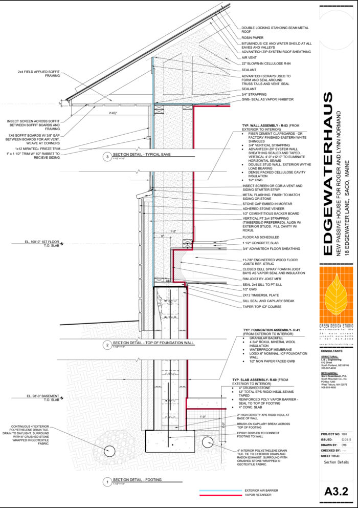
Here’s the wall section that our architect, Chris Briley, has drawn. Overall, we like it. Key aspects:
- Basement floor poured on 8 inches of rigid EPS (a type of rigid foam) subslab insulation (R-41).
- Insulated concrete forms (ICF) basement walls with exterior Roxul insulation (R-40). No additional interior insulation in the basement; the drywall mounts on the ICF foam.
- Double-stud above-grade walls, with the interior wall (called a wythe) load-bearing. The entire 14-inch cavity between the exterior and interior wythes is filled with dense-packed cellulose insulation (R-53).
- Lower exterior wall clad in 1-inch-thick stone veneer, atop a backerboard with a pressure-treated 2X4 attached vertically to allow additional Roxul batts in the 1 1/2-inch cavity for insulation and drainage. Upper portion clad in fiber-cement siding.
- Main floor has a concrete slab floor for thermal mass, though we have backed off using radiant floor heating – we’ve become convinced that’s not cost-effective for such a tightly insulated home.
- Raised-heel roof trusses with the full 24 inch depth of blown-in cellulose extending over the top of the exterior wythe for R-91 – Yikes!
Call the drywall ceiling support that much insulation?
We discussed the details of this cross-section with Chris today. This design has not been tested in the energy model yet, so the R-values my fluctuate up or down.
Meeting the Passivhaus standard requires substantial levels of insulation. Nonetheless, this is more insulation than even I expected in the ceiling. Lynn thinks we could live at the North Pole in a house this tight! Chris said that he believes the required levels to be in this ballpark, and that he wanted to ensure that the engineering review consider the weight of the likely 20 in.+ insulation in detailing the roof trusses and support for the drywall ceiling.
Having the inner wythe be load-bearing provides an great way to provide a thermal break at the intersection of the wood I-joist floor and the exterior wythe. Because lots of solid wood that comes together here, this area is always a weak point in the thermal envelope of a typical home. I had not seen this detail in the many other double-wall cross sections I have seen in magazines. Kudos Chris!
I am leery of how the exterior wythe bears on the 2×12 bottom wall plate with no other support below. Note how the concrete core of the top ICF course flares to the inside to support the load bearing walls and floor I-joists above. Chris designed it this way to maximize insulation at this point, believing that most of the weight of the exterior wythe will transfer to the outer edge of the ICF cement core. Hmm. Though it is the inner wythe that bears the weight of the floors and roof, the exterior wythe will still bear substantial weight: the wall itself, the stone cladding at 14 lbs/sq, ft,, the cementitious backerboard, and the cementitious siding.
We agreed that this detail would be reviewed by both the ICF manufacturer and the engineer who will approve all the structural aspects of our home prior to construction.
Housewrap plus Zip System sheathing provide two layers of defense
Chris includes some 4 inches of high-density EPS foam at the bottom of the ICF core as a means of thermally isolating the concrete core of the ICF with the concrete footer. Interesting, but I’m not sure how much complexity (read material and installation cost) this adds compared to the benefit of a thermal break at this point in the basement.
We spoke about the possibility of the truss manufacturer ending the bottom web (which will be the ceiling of the main floor) at the outer portion of the exterior wythe, while continuing the upper web (which will support the roofing) to the eaves as shown. This would allow continuing the Adventech Zip sheathing without interruption to the bottom of the upper web, rather than fitting and sealing individual pieces of polyiso (a type of rigid insulation). Tightly insulating the cavities where the roof meets the wall is just as challenging as where the floor meets the exterior wall. The upper web will serve as a venting channel for the attic, with intake at the eaves out air flow to a ridge vent.
I also asked Chris to include an air-barrier fabric like Tyvek outside the Adventech Zip sheathing. Although the Zip sheathing is rated as an air barrier when all seams are properly taped, I have read a number of articles expressing concerns about water intrusion if the taped joints fail over time. Dense-packed cellulose could wick any moisture into the cavity, thereby (possibly) causing unseen mold issues. Using the fabric would provide a second level of moisture defense, as well as facilitate sealing around the rough openings for exterior doors and windows.
All in all, we think this is a very well polished design.
The first article in this series was Kicking the Tires on a Passivhaus Project. Roger Normand’s construction blog is called EdgewaterHaus.
Weekly Newsletter
Get building science and energy efficiency advice, plus special offers, in your inbox.


18 Comments
Load Bearing
I have been working on superinsulated design, and have pondered the questions about how the double stud walls carry the load. Are there any other blogs on GBA about this particular issue? My general assumption is that the loading will not equalize between the inner and outer studs, and thus, one or the other must be designated as the load bearing stud, and it must be capable of carrying all of the loading at that double stud location.
How are the window and door headers applied in the wall shown here? Is there a header for the inner studs and another header for the outer studs?
A few questions for Roger (or Chris)
Is is necessary to seal the foam blocking at the eaves, when there is an air vent right above the blocking?
Did you really need to foam the rim joists? I assume it's for r-value and not for sealing purposes?
The Red Line
There is no mention of air tight drywall ... so I am guessing that the wall air barrier is the ZIP system.
and since the attic is vented ... the ceiling air barrier must be the drywall?
I wonder if you have traced a continuous red-line over the air barrier system?
I am not seeing how the ceiling air barrier "connects" to the wall air barrier.
Connecting ZIP to mudsill
It seems to me that if you are doing a ZIP wall air barrier that it would be better to have a CONTINUOUS gasket "connecting" the ZIP to the mudsill...
instead of the intermittent not-so-continuous sealant that is shown
note the CONTINUOUS gasket in the attached John Abrams detail
Good point John.
I had the same thought about the "red line" and how it [doesn't?] transition to the ceiling plane...
I like the vented attic and the framing at the rim board.
Response to Ron Keagle
Ron,
Confusing load paths are sometimes a problem with "double wall" designs so you're right to chose one wall or the other as the load bearing part of the assembly.
Personally, I like the interior wall as the load bearing wall and the exterior wall as a simple "balloon frame".
I have some details posted at my blog which may interest you - there are sections showing how the headers are located:
http://ourhouseuponmoosehill.blogspot.ca/p/details.html
Wall Loading
Lucas,
I looked at your website and see how you are detailing the window openings. Thanks for referencing your structural details. I will spend some time looking them over. I see that you are separating your electrical lines and boxes from the insulation cavity. I plan on doing that too. That looks like a fun project.
What I decided for my design is to use double studs made of 2 X 4s inside and outside, with a total outside dimension of 14”. The entire double stud sits on the floor platform with its outside flush with the outside of the foundation. So the inner row of studs sits slightly inboard from the inside of the foundation wall. So with that arrangement, either the inner studs or the outer ones could carry the load and there would be no way to stipulate which carries the load. The load path of the inner studs would offset the foundation a bit through the floor joists, but I don’t see a problem with that.
The only thing that must be avoided is making the design rely on the inner and outer studs cooperating to share a load that neither one could support alone. So I just figure that either inner or outer studs can carry the load, and it does not make any difference as long as both inner and outer studs each are capable of carrying all on the load at that double stud position. The loading cannot equalize on the inner and outer studs, but it doesn't have to.
In one sense, this loading scheme would require a double header for the windows and doors because either the inner or outer studs can carry the load, and I don’t know which ones will do so. But, then if I omit one of the two headers at a window, and assume the studs with the single header will carry the load, I don’t see a problem with that. By omitting the inner header, I force the outer studs and header to carry the load there, and they will be capable of doing so.
But, ultimately, I decided to use double headers at the windows, because the windows are narrow and there are not that many of them. And I can use the inner header to help with detailing the connections of the pre-fabricated plywood window tunnels, vapor barrier, etc. I omitted the inner header for the doors because that tunnel detailing does not benefit from them, and I want more headroom there.
At last! No more windows! Thanks!
Very cool posting. I loved reading this, and the comments too.
response to comments
Ron (1). Yes, the exterior studs are load bearing, the interior are not. Headers are designed to fit within the outer ‘wythe’ of the double stud wall in very typical fashion (sometimes with multiple jacks flanked by multiple kings depending on window size and header load). The inner ‘wythe’ is not taking load and therefore has no header.
Mike (2). I’m going to send roger the updated wall section. We changed this slightly. We decided to field frame the bottom chord of the eave so that the sheathing could run up to the underside of the top cord where we then vent the cellulose.
John (3). Good call. Again, I’ll send the updated section so by the time most of you are seeing this the correction will already be made. We are infact using the air drywall approach. Furthermore, we are sheathing the underside of the trusses with ½” zip system and installing a ½” gusset at the top of the wall. That way we are sealed and ready to test the shell (blower door) even before insulation. We should have our desired number at that point. (0.6 ACH50) Also we will be able to seal the sheetrock to the zip wall at the ceiling.
John (4). The walls were built in the shop and the sheathing is sealed to the regular sill. SO for us, it was important to seal the mudsill to the regular sill. We did this with a double bead of sealant, though an argument for a gasket could have been made.
Ron (7). Believe me I’ve given plenty of thought about loading interior vs. exterior vs. both. It’s possible to do any. My advice is to remember two things: a) The load will always bear on the most rigid element. If a load is placed on two stud walls the more rigid one will take the load, so you’ll want to be sure you are consistent with your details, you may think, “hey I have TWO headers so they really only have to take half the load.” Not so if all the load is already pounding down one side because the studs were cut just a 1/6” shorter on the other. B) one day, someone is going to renovate that building for some reason or another and KNOWING you can remove one wall or another without worry of collapse is a pretty nice thing.
Bottom plate
Isn't the 2x12 bottom plate a thermal bridge? Why not have two completely separate 2x4 walls for that reason?
Sill Plate
The 2x12 is a bit of a bridge, but since Roger and Lynn wanted a stone exterior wainscot, we took advantage of the extra layer of material turning the stone into a thin stone veneer allowing us to add exterior Roxul insulation over this weak spot. If we separated the sill into two separate sills we'd need twice the anchor bolts and all the fussing of leveling and sealing the sill would have to be done twice. The floor braces the top of the wall and the bottom of the I-jost flanges are liberally nailed into the 2x12 sill. In fact, were I to do this again, I would call for blocking between the rim joist and the 2x4 sill plate just to give the floor diaphragm a means to "push" against the plate that is carrying the vertical load of the house. We did, after all, just have a 4.0 earthquake here in Maine. Weird, but real.
Load Path Details
Chris,
Thanks for the information concerning my questions. Just to clarify, I am not proposing a double header in which each header is intended to share the load, and therefore, each header sized for half the total load. I understand your point about how the load path will not predictably divide between two identical walls.
What I have developed for my application is two walls that are positioned to share a load, but if one assumes more loading than the other, it will be okay because each wall is capable of carrying the full load. I just don’t stipulate which wall must carry the load.
I raised the question about load paths in your design because I understood that the inner stud of the double stud is load bearing and the outer stud is not load bearing.
That interpretation is based on Roger’s statement:
“Having the inner wythe be load-bearing provides an great way to provide a thermal break at the intersection of the wood I-joist floor and the exterior wythe.”
It also indicates the loading on the inner studs in the drawing callout for the wall detail: “DOUBLE STUD WALL. INTERIOR - WYTHE LOAD.”
However, if the outer stud is load bearing, as you clarify, I am a little confused about the detail of how the outer studs bear on the foundation. It appears that the majority of the loading is directly above the foam, and would need to transfer to the concrete by cantilever across the 2 X 12. Can you clarify that point?
loads
At the moment, Roger's blog is historical. Reprints form is ongoing blog at edgewaterhaus.com. This excerpt was from a while back when we were deciding which wall system to use (or whether to be interior load bearing or exterior.) Our load is through the exterior, which also has the sheathing making it the most appropriate for the task (as those loads are then braced laterally by the sheathing).
At the point of bearing at the top of the foundation wall, you'll notice we are using a taper-top course. This has only 3/4 of EPS insulation on the outermost part, meaning the load bearing wall only cantilevers 3/4". Vertical loads can travel through homogeneous material up to 45 degree angles so the load from the outer stud is easily transferred through the plates and into the reinforced concrete.
Separate sills for each wall
John, do you mean like this:
The concrete guy had no problem with a second set of sill bolts. Another thought I had is that it might be easier to ensure good contact and compression between sill, sill sealer, and foundation with separate sills. I wonder about wood movement over time with a very wide sill (2x12).
Loading the taper in the concrete
Chris,
You say the loading is through the exterior studs, and refer to it transferring down through the taper-top course of the foundation wall. I see the tapered top course, but that is on the interior, not the exterior. So I don’t follow your explanation.
It's not the concrete guys
Ron, I don't think you're seeing it correctly. Just above the #2 "Section Detail" tag it clearly shows the ICF inner wall tapering outward.
Dick, I wouldn't expect the concrete guy to have an issue with placing a second set of bolts. It's the carpenters you have to consider. It's enough work to get one plate marked, drilled and set level and square. To do it for two parallel plates could be twice as much work. On the other hand, trying to find pressure treated 2x12's straight enough to use as plates could be tough. With 2x6's and 2x8's you can muscle them straight.
Chris,
You have apparently
Chris,
You have apparently switched the taper from the inside to the outside since I asked my question. It is on the outside now, but I have it saved from earlier, and it is on the inside in that version. Roger should revise his text to match. In any case, your new drawing makes it clear. Thanks.
Air Vent Question:
Does that air vent above the insulation have an inlet and outlet? If so, how are those details arranged?
Log in or create an account to post a comment.
Sign up Log in